Methods of forming a nebulizing catheter

a nebulizing catheter and catheter tube technology, applied in the direction of medical atomizers, inhalators, surgical instruments for heating, etc., can solve the problems of limited medication delivery rate, efficiency and control, limited use and application, and substantial portion of medicine not being delivered to the lungs, so as to achieve control and efficiency the effect of medicine delivery

Inactive Publication Date: 2009-01-06
TRUDELL MEDICAL
View PDF159 Cites 120 Cited by
  • Summary
  • Abstract
  • Description
  • Claims
  • Application Information

AI Technical Summary

Problems solved by technology

Although delivery of medication via the respiratory tract has been used for many years, there are difficulties associated with prior systems that have limited their use and application.
For example, conventional methods have provided for only limited medication delivery rates, efficiency, and control.
Conventional methods for aerosol delivery result in a substantial portion of the medicine failing to be delivered to the lungs, and thereby possibly being wasted, or possibly being delivered to other parts of the body, e.g. the trachea.
Inhalers typically provide only limited delivery of medication to the lungs since most of the medication is deposited on the linings of the respiratory tract.
A significant amount of the aerosolized medication may be deposited inside the endotracheal tube and the delivery rate of the medicine to the lungs also remains relatively low and unpredictable.
The low and unpredictable delivery rates of prior aerosol delivery systems have limited the types of medications that are delivered via the respiratory tract.
For new medications that are relatively expensive, the amount of wasted medicine may be a significant cost factor in the price of the therapy.
Another consideration is that some aerosols delivered to the lungs may have adverse side effects, e.g. radioactive tracers used for lung scans.
The prior methods of aerosol delivery not only were inefficient, but also did not provide a reliable means to control precisely the dosage being delivered.

Method used


Image

  • Methods of forming a nebulizing catheter
  • Methods of forming a nebulizing catheter
  • Methods of forming a nebulizing catheter

Examples


first embodiment

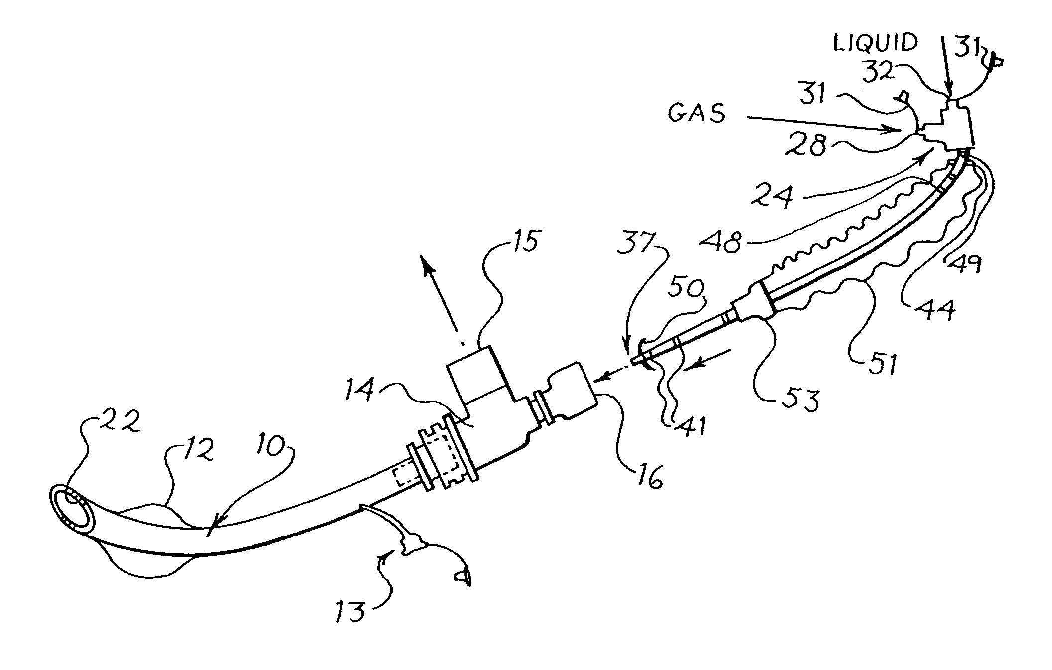
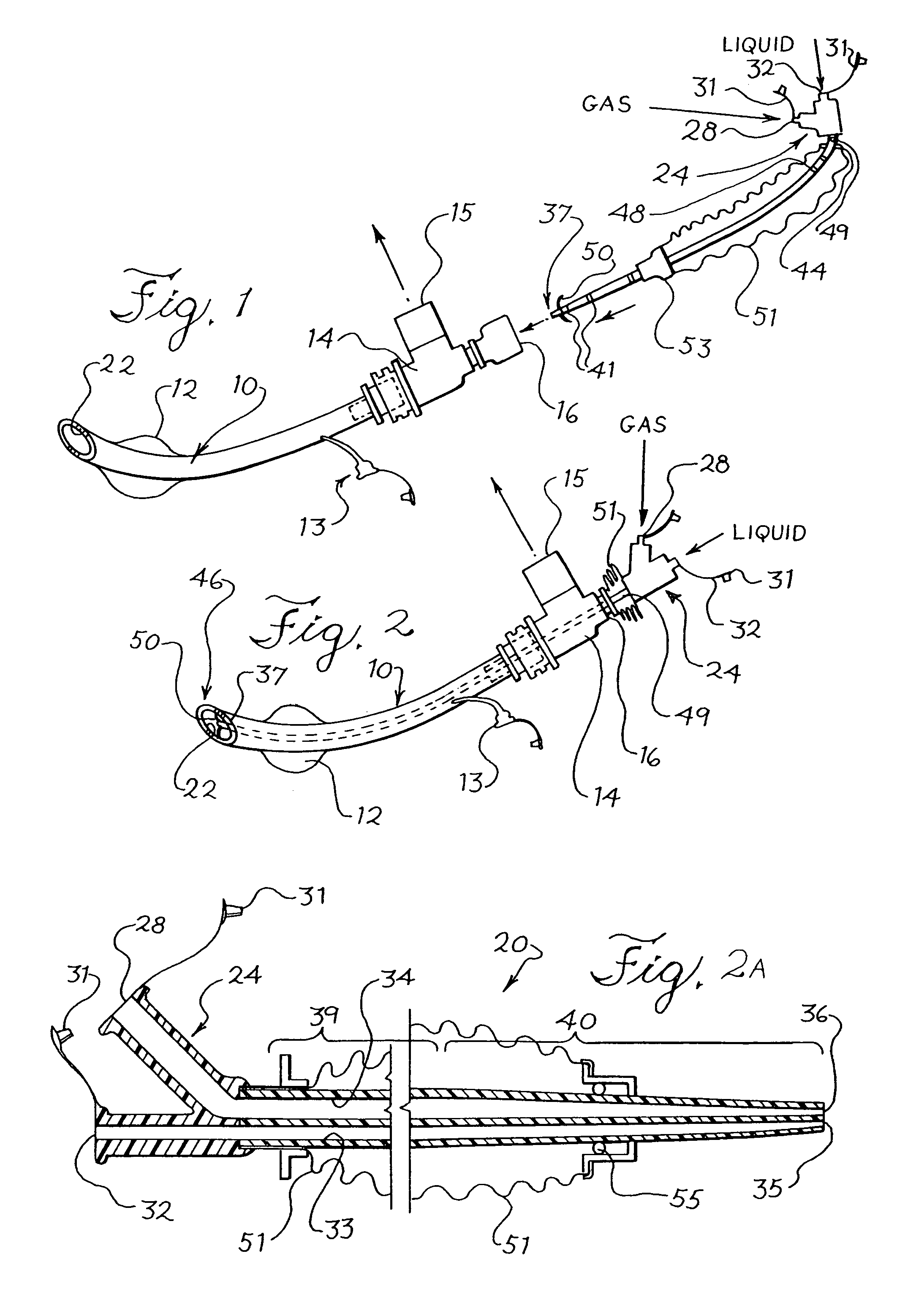
[0094]Referring to FIGS. 1 and 2, there is depicted the present invention. FIGS. 1 and 2 show an endotracheal tube 10 which may be a conventional endotracheal tube. The endotracheal tube 10 may have an inflatable cuff 12 located close to its distal end to facilitate positioning the tube 10 in the patient's trachea, or alternatively the endotracheal tube 10 may be of a type without an inflatable cuff. The inflatable cuff 12 is connected via a separate inflation lumen in the endotracheal tube 10 to a proximal fitting 13 for connection to a source of inflating gas (not shown). The endotracheal tube 10 has a proximal end connected to a manifold fitting 14. The fitting 14 has a port 15 suitably adapted for connection to a ventilator circuit (not shown). The fitting 14 also includes another port 16 that permits the introduction of a separate catheter into the endotracheal tube from the proximal end. The fitting 14 may be similar in construction to the elbow fitting described in U.S. Pat. ...

embodiment 136

[0125]FIGS. 12 and 13 show an alternative embodiment 136 of the multiple lumen nebulization catheter in FIG. 11. The embodiment in FIGS. 12 and 13 is useful when it is desired to provide the aerosol medicine with a pulsed delivery. The pulsed delivery may be timed to coincide with the inhalation of the patient so that aerosol is not wasted when the patient is exhaling. A potential drawback with pulsed delivery is that the aerosol may drool from the tip of the nebulizing catheter when the pressure being applied to the liquid is reduced to effect the pulsation. To avoid this potential problem, the nebulizing catheter 136 provides for closure of the liquid lumen when the pressure being applied to it is reduced. As in the previously described embodiment, the nebulization catheter 136 in FIGS. 13 and 14, has a centrally located lumen 137 for delivery of a liquid medicine and a plurality of lumens 138 surrounding the central lumen 137 for conveyance of a pressurized gas to nebulize the li...

embodiment 252

[0133]In a manner similar to the embodiments 208 and 236 of FIGS. 16 and 17, in the embodiment 252 of FIGS. 18 and 19, the distal tip of the retractable wire 292 can extend distally from the distal liquid orifice 288 in order to minimize particle size, or alternatively may not extend distally of the distal liquid orifice 292. In one embodiment, the distal tip of the retractable wire may extend distally of the liquid orifice 288 by approximately 0.2 mm.

[0134]FIG. 20 shows another embodiment of a nebulizing catheter. In this embodiment, a nebulizing catheter 296 has a main shaft portion 300 with a gas lumen 304 adjacent to a liquid lumen 308. The gas and liquid lumens 304 and 308 flow into a distal cavity 312. The distal cavity 312 is formed by an outer tubular extension 316 that extends distally over and past a distal end 320 of the main shaft portion 300. A filter 324 is located in the liquid lumen 308 to filter out any particles in the liquid. The liquid lumen 308 has a step down i...


PUM


Abstract

A method and apparatus for delivering a medicine to a patient via the patient's respiratory system with control and efficiency. A nebulization catheter is positioned in the patient's respiratory system so that a distal end of the nebulization catheter is in the respiratory system and a proximal end is outside the body. In a first aspect, the nebulization catheter may be used in conjunction with an endotracheal tube and preferably is removable from the endotracheal tube. The nebulization catheter conveys medicine in liquid form to the distal end at which location the medicine is nebulized by a pressurized gas or other nebulizing mechanism. The nebulized medicine is conveyed to the patient's lungs by the patient's respiration which may be assisted by a ventilator. By producing the aerosol of the liquid medicine at a location inside the patient's respiratory system, the nebulizing catheter provides for increased efficiency and control of the dosage of medicine being delivered. In further aspects of the nebulizing catheter apparatus and method, alternative tip constructions, flow pulsation patterns, centering devices, sensing devices, and aspiration features afford greater efficiency and control of aerosolized medicine dosage delivery.

Description

REFERENCE TO RELATED APPLICATION[0001]This application is a divisional of U.S. application Ser. No. 09 / 265,603, filed Mar. 10, 1999, now U.S. Pat. No. 6,739,334 which is a continuation of U.S. application Ser. No. 08 / 787,813, filed Jan. 23, 1997, now U.S. Pat. No. 5,964,223, which is a continuation of U.S. application Ser. No. 08 / 261,866, filed Jun. 17, 1994, abandoned, and the entirety of each of these applications is hereby incorporated herein by reference.[0002]The present application incorporates by reference U.S. application Ser. No. 08 / 261,490, entitled “IMPROVED CATHETER SYSTEM FOR DELIVERY OF AEROSOLIZED MEDICINE FOR USE WITH PRESSURIZED PROPELLANT CANISTER” filed Jun. 17, 1994, now U.S. Pat. No. 5,642,730.BACKGROUND OF THE INVENTION[0003]The present invention relates to aerosol delivery of medication to the lungs and more particularly, the present invention relates to delivery systems for application of nebulized medication to the lungs with improved delivery rates, efficie...

Claims


Application Information

Patent Timeline
Patent Type & Authority Patents(United States)
IPC IPC(8): A61B18/08A61M11/06A61M15/00A61M16/04A61M25/00B67D7/06
CPCA61M16/0463A61M25/003B67D7/06A61B19/34A61M11/06A61M2209/10A61M25/0009A61M25/0068A61M25/0071A61M2025/0035A61M2025/0036A61M2025/0037A61M2025/0039A61M2025/004A61M2025/0073A61M2205/0266A61M15/00A61M11/005A61M11/001A61B90/70A61M15/025A61M16/0486A61M16/0404A61M16/042A61M16/0484
Inventor BARAN, GEORGE
Owner TRUDELL MEDICAL
Why Eureka
Try Eureka