HME shuttle system

a shuttle system and shuttle technology, applied in the field of mechanical ventilators, can solve problems such as achieving their maximum potential, and achieve the effect of improving physiological gas flow characteristics

Inactive Publication Date: 2009-12-22
FENLEY ROBERT C
View PDF6 Cites 79 Cited by
  • Summary
  • Abstract
  • Description
  • Claims
  • Application Information

AI Technical Summary

Benefits of technology

[0007]An HME Filter is disclosed having an integral housing that improves physiological gas flow characteristics delivered in a patient's ventilator circuit. This is accomplished by using a minimalist approach eliminating components at the circuit “Y” connector. It maintains a closed circuit gas flow whether an internal filter material is or is not engaged and with or without a nebulizer aerosolizing medications. When an HME filter is desirable for optimal patient care, the HME SHUTTLE will continue to maintain the same closed circuit gas flow during the HME filter materials insertion into the HME SHUTTLE, throughout the course of the HME filter's use in the closed gas flow circuit and during the HME filter materials removal from the HME SHUTTLE. The placement for optimal patient care is to be located between the connection of inhalation and exhalation sides of mechanical ventilator circuit and endotracheal tube of an intubated patient. In addition to the HME SHUTTLE primary utility of functioning with or without an HME filter, it also accommodates the docking port for the use of a nebulizer external to this device's specification.
[0014]6. Facilitates in the use of and maximizes inline nebulizer therapies by placing HME Shuttle in “Open Mode” minimizing resistance to aerosol flow.
[0016]8. Lowers a patient's peak airway pressure during suctioning when placing HME Shuttle in “Open Mode” preventing direct HME filter contamination of any secretion that might move around a suction catheter.

Problems solved by technology

Yet, inherent drawbacks (i.e. breaking the closed gas flow circuit while using an HME filter) remain in their delivery system that still prevent them from achieving their maximum potential.

Method used


Image

  • HME shuttle system
  • HME shuttle system
  • HME shuttle system

Examples


Embodiment Construction

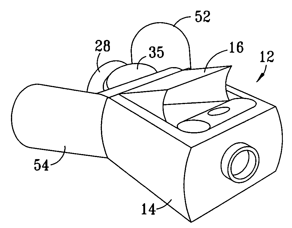
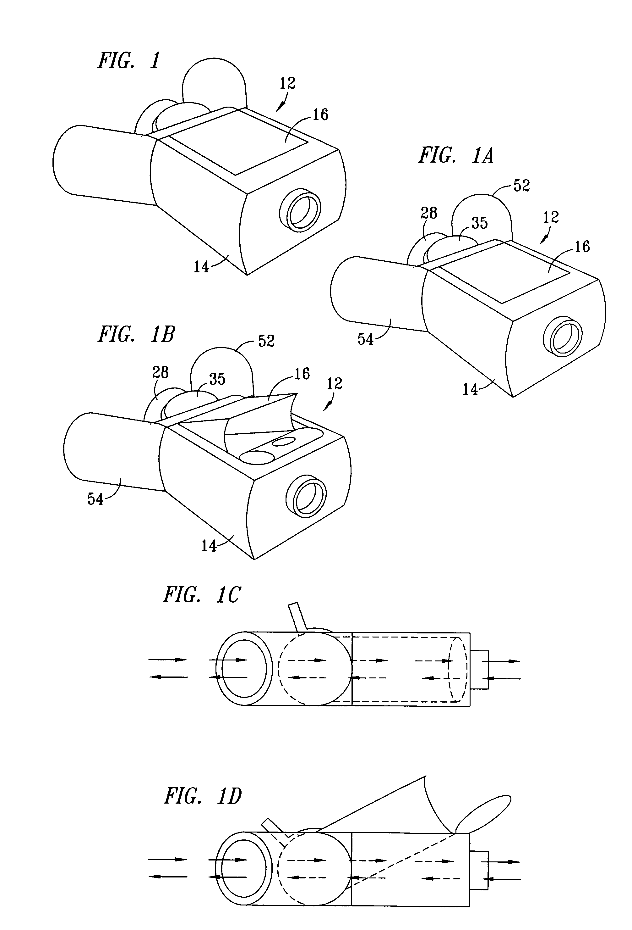
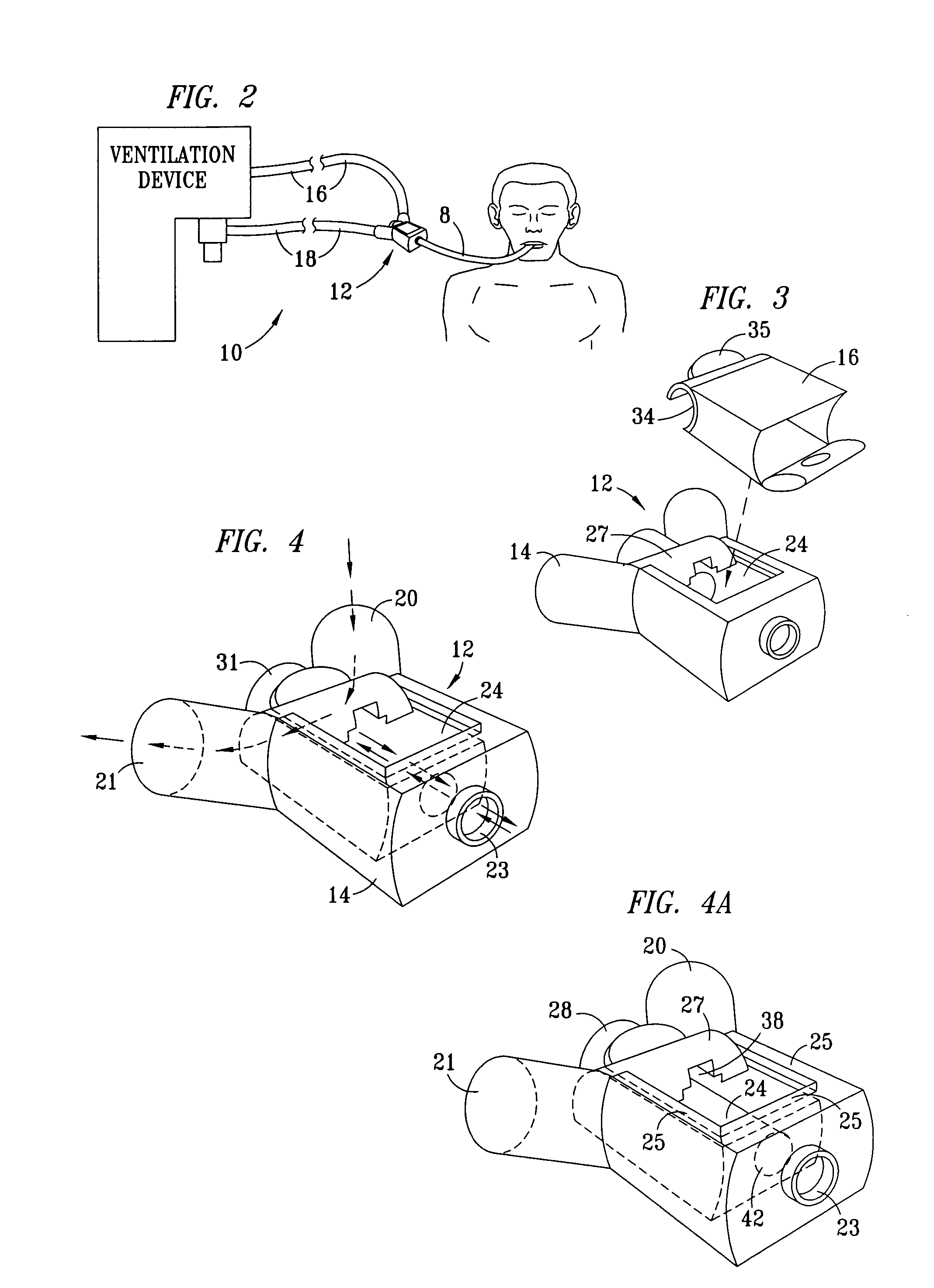
[0052]The HME SHUTTLE for optimal patient benefit is to be placed between a ventilator circuit and patient's endotracheal tube once a patient is intubated.

[0053]The HME SHUTTLE is designed to accommodate the use of one single patient use disposable HME Filter (FIG. 7) manufactured specifically for this device. However, the insertion of an HME Filter is not mandatory to maintain proper HME SHUTTLE function.

[0054]This option creates the HME SHUTTLE's duel operation modes: (1) “Open Mode” (FIG. 1B) when a medical gas passes freely through the HME SHUTTLE from the mechanical ventilator's circuit to the patient during inhalation bypassing the HME Filter and during exhalation, gases pass from patient through the HME SHUTTLE to ventilator's circuit bypassing the HME Filter. Or, (2) “Closed Mode” (FIG. 1A) when a medical gas passes through the HME SHUTTLE, including its HME Filter from the mechanical ventilator's circuit to the patient during inhalation and during exhalation gases pass from...


PUM


Abstract

An HME Filter is provided having with an integral housing having minimal components which eliminating components at the circuit “Y” connector. A closed circuit gas flow is maintained whether an internal filter material is or is not engaged, and with or without a nebulizer aerosolizing medications. The HME SHUTTLE continues to maintain the same closed circuit gas flow during the HME filter materials insertion into the HME SHUTTLE, throughout the course of the HME filter's use in the closed gas flow circuit and during the HME filter materials removal from the HME SHUTTLE. The placement for optimal patient care is to be located between the connection of inhalation and exhalation sides of mechanical ventilator circuit and endotracheal tube of an intubated patient. The HME SHUTTLE also accommodates the docking port for the use of an external nebulizer.

Description

CROSS-REFERENCE TO RELATED APPLICATION[0001]The present application claims priority to and is a continuation in part of U.S. Provisional Application Ser. No. 60 / 699,778, filed Jul. 15, 2005, entitled HME Shuttle System, invented by Robert C. Fenley.TECHNICAL FIELD OF THE INVENTION[0002]The present invention relates in general to mechanical ventilators for medical use, and in particular to heat moisture exchange filters.BACKGROUND OF THE INVENTION[0003]Adequate humidification of oxygen to a person's lungs has long been recognized as an essential component for maintenance of a healthy pulmonary system. In a healthy individual, traditionally, this is accomplished by an integral relationship between a person's upper airways in general and multiple functions of nasal pathways in particular. For those individuals where their medical conditions require some form of assistance from artificial respiration provided by a mechanical ventilation device, these biological structures used for prope...

Claims


Application Information

Patent Timeline
Patent Type & Authority Patents(United States)
IPC IPC(8): A62B18/08
CPCA61M16/0816A61M16/0833A61M16/1045Y10S128/909A61M16/1055A61M16/0093A61M16/107
Inventor FENLEY, ROBERT C.
Owner FENLEY ROBERT C
Why Eureka
Try Eureka