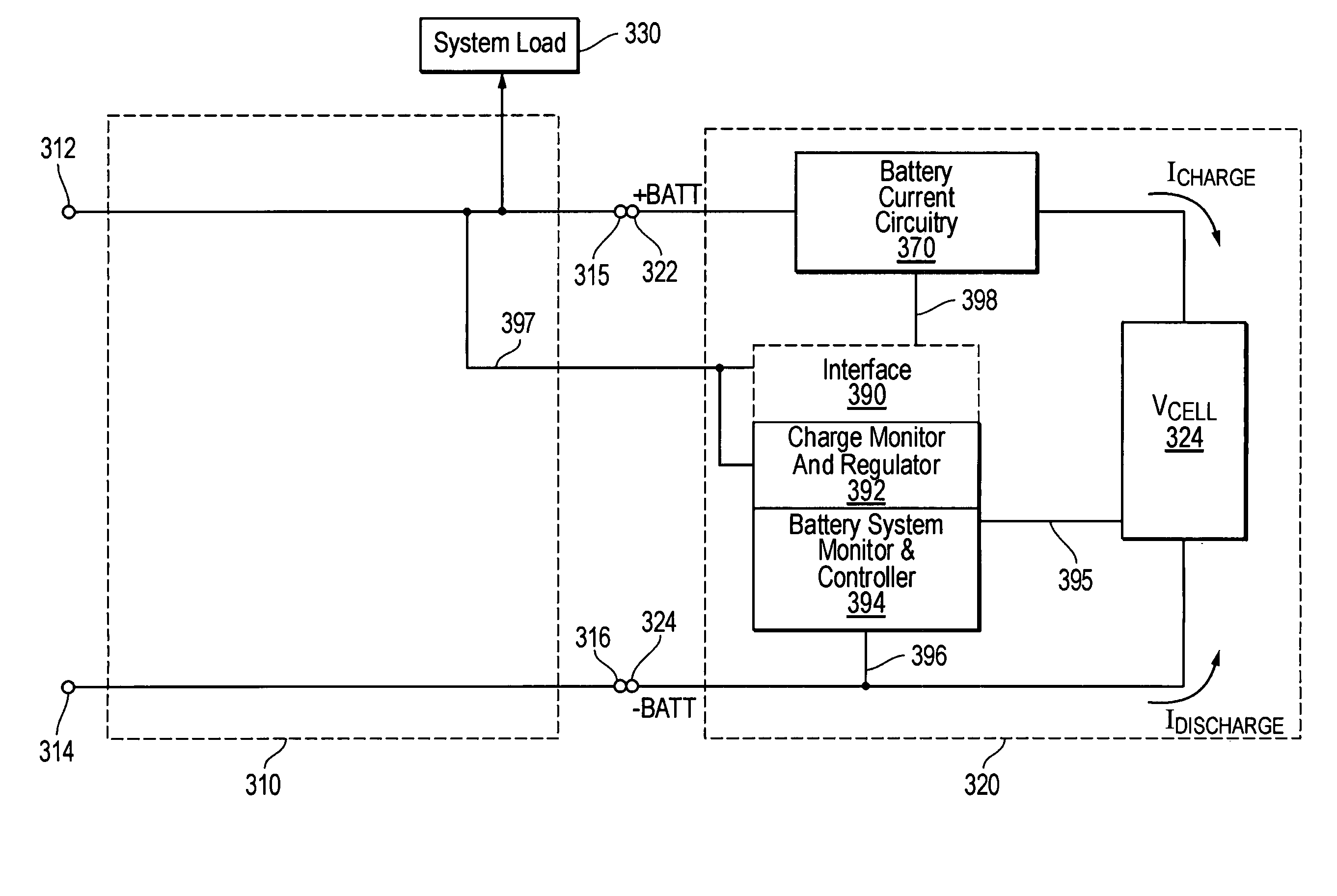
[0014]Disclosed herein are systems and methods for integrating one or more charger regulation tasks (e.g., one or more of those tasks typically performed by charger regulator circuitry of a separate battery charging apparatus) within a battery system (e.g., within a BMU of a battery pack of a portable information handling system). Advantageously, the disclosed systems and methods may be implemented in one embodiment as a relatively low cost scheme for integrating charger regulation tasks within a battery system, such as a battery pack of a portable information handling system. In this regard, traditional component / s of the battery system (e.g., BMU microcontroller and FET components of a battery pack) may be leveraged to realize charger regulator functionality within the battery system rather than within a separate battery charging apparatus. For example, the disclosed systems and methods may be implemented in one embodiment to utilize a BMU microcontroller of a battery system (e.g., battery pack of a portable information handling system) to adjust charging current and voltage, thus eliminating the need for the provision of a separate charger controller within charger regulation circuitry of an associated battery charging apparatus. In such an embodiment, microcontroller BMU utilization efficiency may be increased, and system cost reduced.
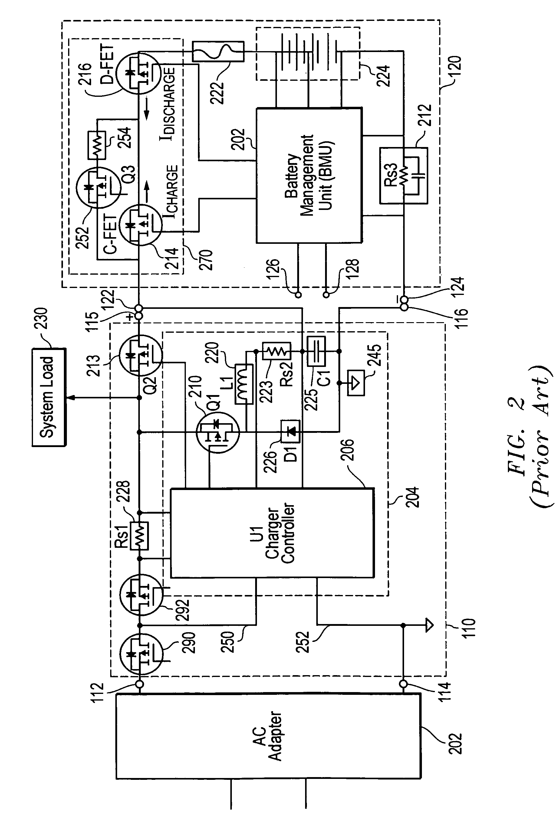
[0015]Such an implementation allows for the elimination of multiple components from a battery charging apparatus (e.g., FETs 210, 213 and 252, resistor 254, current sensor resistor 223, and charger controller 206 of conventional battery charging apparatus 110 of FIG. 2), leading to substantial cost savings. This makes possible the elimination of duplicated / redundant components in the charge and discharge current paths of a conventional battery apparatus and battery system combination, such as illustrated in FIG. 2. For example, FET 210 and FET 214 of FIG. 2 have duplicated function during charging of battery cell / s 224, in that controlled charge current (power flow) is flowing though both FETs 210 and 214. Similarly, when battery cell / s 224 are supplying power, FET 213 and FET 216 have a similar redundant discharge function, in that discharge current flow is flowing through both FETs 213 and 216. A similar redundant situation exists with respect to current sense resistors 223 and 212 of FIG. 2. Similarly, with regard to the redundancy of charger controller 206 and BMU 202 of FIG. 2, as previously described resource utilization of BMU 202 of FIG. 2 may be lower than 10% in terms of memory, registers, calculation capability, etc. Using the disclosed systems and methods makes it possible to use a BMU to control battery charging parameters instead of using a separate independent charger controller. Thus, in addition to reducing hardware costs, the disclosed systems and methods also allow reduction in costs associated with controller software / firmware.
[0016]In a further embodiment, pre-charge circuitry tasks may also be implemented within the battery system (e.g., battery pack of a portable information handling system) by using a pre-designed current control mode. Such a pre-designed current control mode may be implemented to eliminate the need for separate pre-charge circuitry components (e.g., FET 252 and resistor 254 of conventional battery charging apparatus 110 of FIG. 2) leading to further cost savings.
[0017]In one embodiment, the disclosed systems and methods may be implemented by incorporating a relatively small amount of logic and interface circuitry into the BMU of a battery system (e.g., battery pack of a portable information handling system) to provide the ability to monitor system voltage and current in real time, and the ability to dynamically control required charge current to the battery cell / s of the battery system. In one exemplary embodiment, a relatively small amount of logic circuitry may be integrated into the BMU microcontroller chip to provide these abilities.
[0018]In the implementation of various embodiments of the disclosed systems and methods one or more advantages may be achieved over existing conventional rechargeable battery configurations. Examples of these advantages include, but are not limited to, cost savings (e.g., $2 / unit), printed circuit board (PCB) space savings (e.g., reduction in required PCB space of greater than 500 mm2), reduced power loss or dissipation due to decreased components, improved ease of implementation of specific switching mode maintenance charge and / or pre-charge current modes, increased flexibility and cost effectiveness due to digital control (e.g., platform design flexibility and cost-effectiveness, reduced time to market), avoidance of analog tolerance issues (e.g., aging, temperature effects, drift, offset, etc.), improved reliability by monitoring external system voltage, current and internal battery variables.
[0022]In another respect, disclosed herein is a method of charging one or more battery cells of a battery system coupled to a battery charging apparatus, including: receiving a charging current in the battery system from the battery charging apparatus, the battery system including charge regulation circuitry integrated within the battery system and the integrated charge regulation circuitry including a microcontroller; and using the microcontroller of the integrated charge regulation circuitry to regulate the charging current received in the battery system and to manage operation of the battery system.

