Waveguide antenna front end

a waveguide and antenna technology, applied in the field of radio frequency antenna front end front end, can solve the problems of time-consuming and tedious process, and achieve the effect of reducing the required dimension of the material block

Active Publication Date: 2010-04-29
PANASONIC AVIONICS CORP
View PDF6 Cites 43 Cited by
  • Summary
  • Abstract
  • Description
  • Claims
  • Application Information

AI Technical Summary

Benefits of technology

[0023]According to some embodiments of the invention, at least one of the filters includes a channel with two bends, so as to reduce a required dimension of the material block.

Problems solved by technology

A system formed from components with tuning screws generally requires tuning to electrically match the system components after they are connected together, in addition to tuning the separate system components, which may be a time-consuming and tedious process.

Method used


Image

  • Waveguide antenna front end
  • Waveguide antenna front end
  • Waveguide antenna front end

Examples


examples

[0097]Reference is now made to the following examples, which together with the above descriptions illustrate some embodiments of the invention in a non limiting fashion.

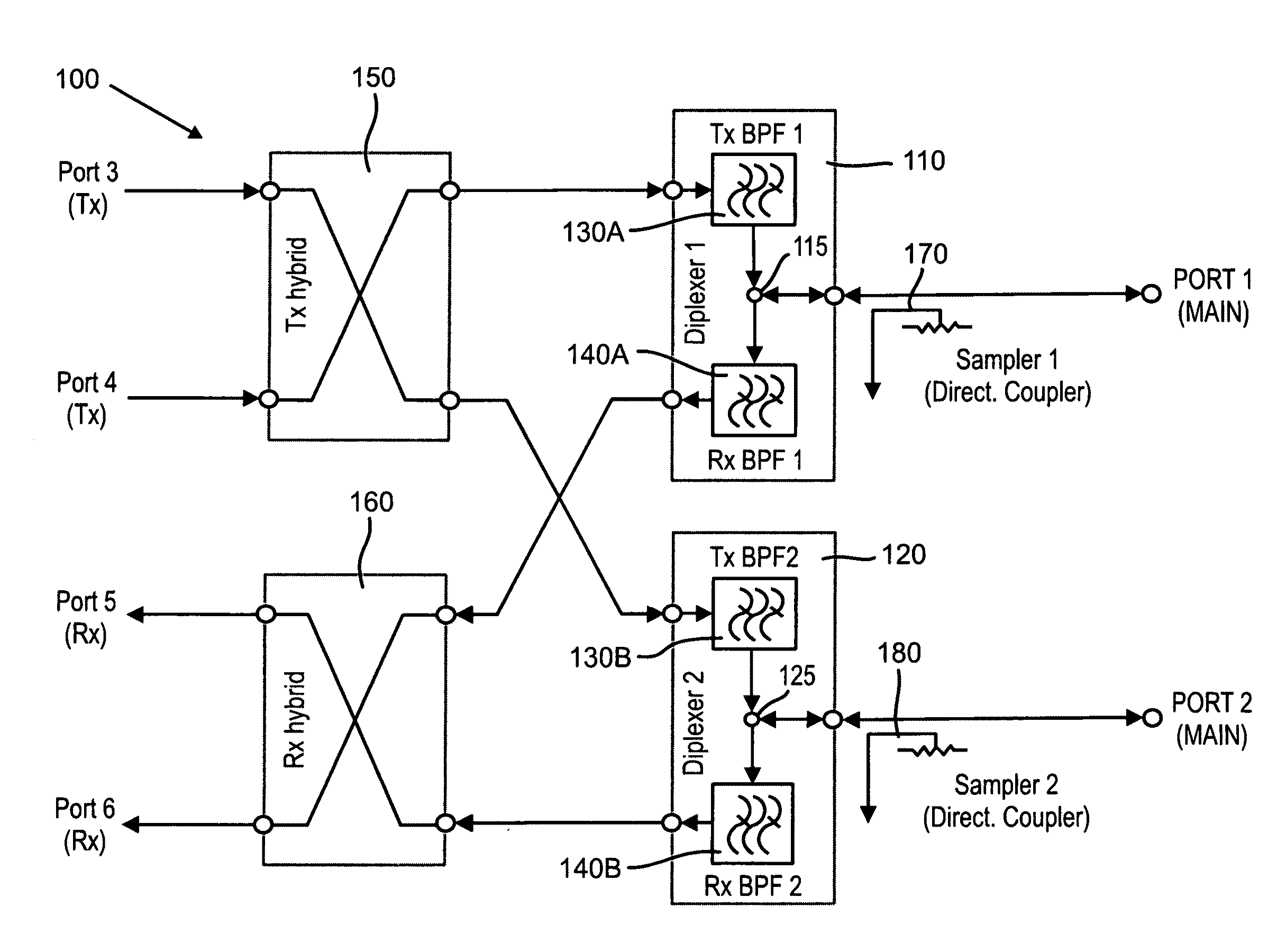
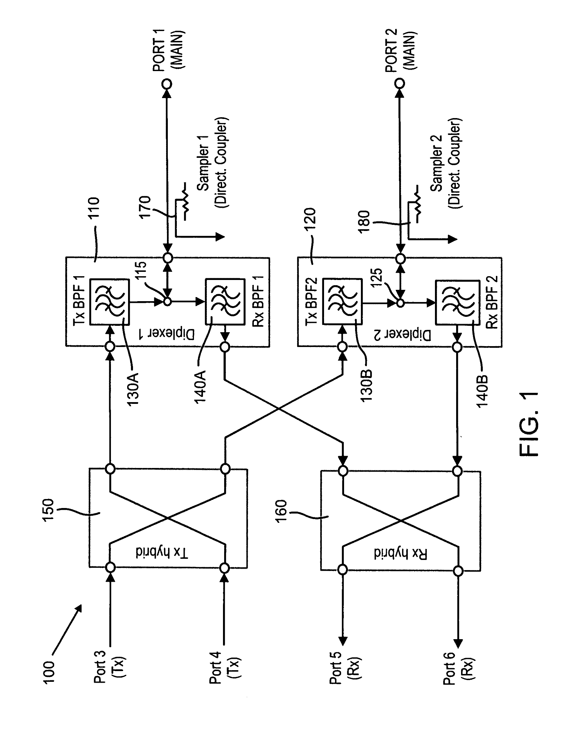
[0098]FIGS. 8-10 show simulated and measured levels of insertion loss and isolation obtained for an embodiment of a front end designed as shown in FIG. 1. In the discussion of FIGS. 8-9, the 3 dB splitting ratio in the Rx and Tx hybrid couplers is not considered as loss.

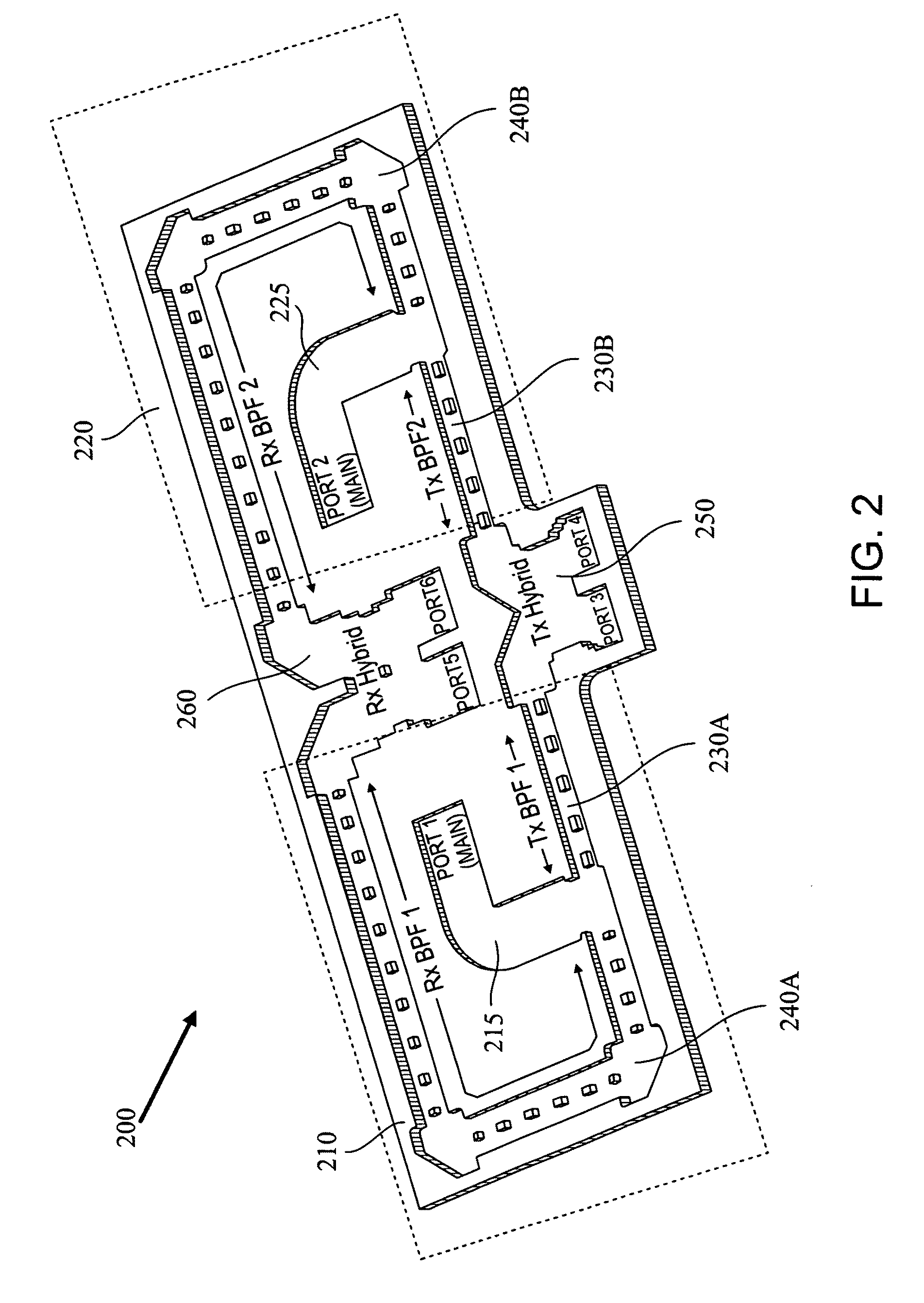
[0099]The Ku-band front end has a receive bandwidth of 10.7-12.75 GHz and a transmit bandwidth of 14-14.5 GHz. Measured results were obtained for a prototype manufactured using CNC machining. The front end is a compact unit arranged in a flat planar design, which fits into an aluminum block of 27 cm×11 cm×1 cm. These dimensions, and specifically the 1 cm height, may not be achievable if standard waveguide flanges are incorporated in the assembly. Note that a typical waveguide flange (WR62) has a 3.2 cm×3.2 cm cross section, so that the total front end...


PUM


Abstract

In some embodiments of the present invention, an antenna front end includes at least two diplexers. Each of the diplexers is defined with a channel within a single material block. Each channel is shaped to provide a diplexer which includes a coupler, a receive band filter and a transmit band filter, which are adjoined and matched to form a continuous waveguide channel. Some embodiments further include a transmit hybrid coupler and/or a receive hybrid coupler. The transmit hybrid coupler is formed as a channel within the material block and adjoined and matched to the two transmit band filters. The receive hybrid coupler is formed as a channel within the material block and adjoined and matched to the two receive band filters.

Description

FIELD AND BACKGROUND OF THE INVENTION[0001]The present invention, in some embodiments thereof, relates to a radio frequency (RF) antenna front end front end, and, more particularly, but not exclusively, to an RF waveguide module which incorporates multiple RF components.[0002]Some RF signal processing is performed using waveguide (WG) components. These waveguide components are often provided with protruding flanges which serve for connecting the separate components together. These flanges may protrude several centimeters from the rest of the component, increasing the size of a system formed by connecting multiple components together by their flanges. Waveguide components connected by flanges typically require integration after the components are connected together.[0003]Additionally, some microwave components, such as waveguide filters, include tuning screws. These tuning screws are used to adjust the electrical properties of the waveguide modules within a filter (e.g. by changing t...

Claims


Application Information

Patent Timeline
Patent Type & Authority Applications(United States)
IPC IPC(8): H01P1/213H01P5/19
CPCH01P1/211H01P5/19H01P1/2138B33Y80/00
Inventor ENGEL, BENJAMIN M.
Owner PANASONIC AVIONICS CORP
Why Eureka
Try Eureka