Pneumatic tire

a technology of pneumatic tires and pneumatic cylinders, applied in the field of pneumatic tires, can solve problems such as the change of steering performance, and achieve the effect of reducing the stiffness of the belt structur

Inactive Publication Date: 2009-01-06
THE GOODYEAR TIRE & RUBBER CO
View PDF7 Cites 1 Cited by
  • Summary
  • Abstract
  • Description
  • Claims
  • Application Information

AI Technical Summary

Benefits of technology

[0008]In another aspect of the invention, the belt structure has more than two cord reinforced plies. When the belt structure has more than two plies, the overall stiffness gradient between the innermost and outermost belt plies is in the desired range of 12 to 25%. The stiffness gradient between directly adjacent belt plies should be equal to each other and / or the stiffness gradient should decrease in the radially outward direction of the tire to create a step-down effect and gradual decrease in stiffness of the belt structure from the interior of the tire to the exterior of the tire.
[0009]In another aspect of the disclosed invention, the carcass structure has at least one carcass reinforcing ply and has at least one pair of sidewall wedge inserts, with a single wedge insert in each tire sidewall. The wedge inserts provide the tire with self-supporting run-flat capabilities.

Problems solved by technology

Steering performance can change over time, mainly deteriorating as components in the vehicle steering system wear, age, or suffer damage.

Method used


Image

  • Pneumatic tire
  • Pneumatic tire

Examples


Embodiment Construction

[0011]The following language is of the best presently contemplated mode or modes of carrying out the invention. This description is made for the purpose of illustrating the general principles of the invention and should not be taken in a limiting sense. The scope of the invention is best determined by reference to the appended claims.

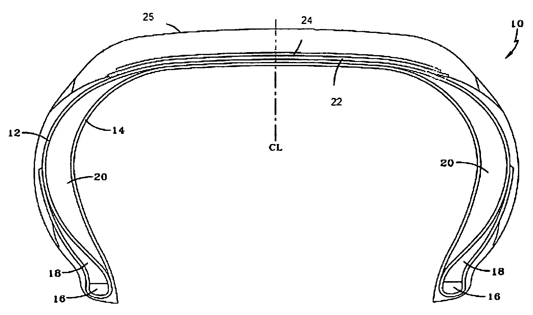
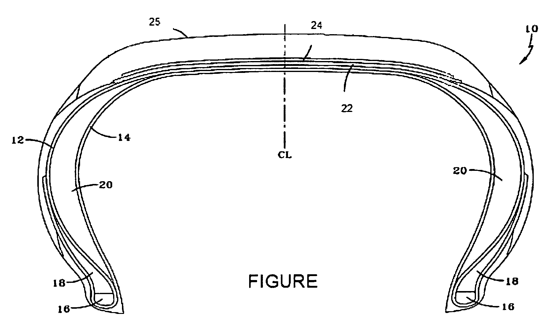
[0012]Illustrated in the FIGURE is a cross-sectional view of a self-supporting pneumatic runflat tire 10. Although not limited thereto, the illustrated tire 10 is of an intermediate aspect ratio. It has a carcass structure comprising a carcass reinforcing ply 12, a gas-impervious inner liner 14, a pair of beads 16, a pair of bead filler apexes 18, and a pair of sidewall wedge inserts 20. Each sidewall wedge insert 20 is located between the carcass reinforcing ply 12 and the inner liner 14. It will be appreciated by those skilled in the art that for self-supporting tires, multiple reinforcing plies may be employed as carcass reinforcing plies, as well as...


PUM

PropertyMeasurementUnit
anglesaaaaaaaaaa
aspect ratioaaaaaaaaaa
speed capabilityaaaaaaaaaa

Abstract

A pneumatic radial tire has a carcass structure, a belt structure, and a tread. The belt structure has at least two plies of reinforcing cords, the cords in the at least two plies being inclined at angles greater than 5° relative to the tire centerline. The cords in the belt plies are inclined at equal but opposite directions relative to the tire centerline. The belt plies have a stiffness variation in the circumferential and meridional directions of the belt plies wherein the stiffness variation is in the range of 12 to 25% between a radially outermost belt ply and a radially innermost belt ply.

Description

FIELD OF THE INVENTION[0001]The present invention is directed to pneumatic tire. More specifically, the present invention is directed to a pneumatic radial tire having a particular defined belt construction. The belt construction is useful for both conventional pneumatic tires and pneumatic tires designed for run-flat operations.BACKGROUND OF THE INVENTION[0002]The term “steering performance” (or simply “steering”) refers to a vehicle driver's feeling that a vehicle's steering (and / or “handling”) is responsive to movement of the steering wheel. The better the steering performance, the better the driver's “feeling” of having control over the vehicle's steering. Because it relates to a “feeling” on the part of a driver, steering performance is essentially a subjective evaluation of a vehicle's steering. Steering performance can change over time, mainly deteriorating as components in the vehicle steering system wear, age, or suffer damage. Steering system components include the steerin...

Claims


Application Information

Patent Timeline
Patent Type & Authority Patents(United States)
IPC IPC(8): B60C9/18B60C9/28
CPCB60C9/2009B60C17/0009Y10T152/10765Y10T152/10801
Inventor MUNSTER, JOHN CHRISTIAN MATHIASHANSEN, ROMAIN FERNANDCLOSE, ROLAND PAUL
Owner THE GOODYEAR TIRE & RUBBER CO
Why Eureka
Try Eureka