
Deployment system and method for subsurface launched unmanned aerial vehicle

a technology for unmanned aerial vehicles and deployment systems, which is applied in the field of subsurface launched unmanned aerial vehicles (uavs), can solve the problems of compromising the platform location, compromising the position, and slowing down the speed of uav systems, so as to facilitate the sliding movement

Inactive Publication Date: 2009-01-06
NAVAL UNDERSEA WARFARE CENT THE UNITED STATES OF AMERICA
View PDF27 Cites 57 Cited by
  • Summary
  • Abstract
  • Description
  • Claims
  • Application Information

AI Technical Summary

Benefits of technology

[0009]It is a further object of the present invention to provide a deployment system adapted to accommodate delayed deployment of the surface platform and launching of the UAV without a flame datum.
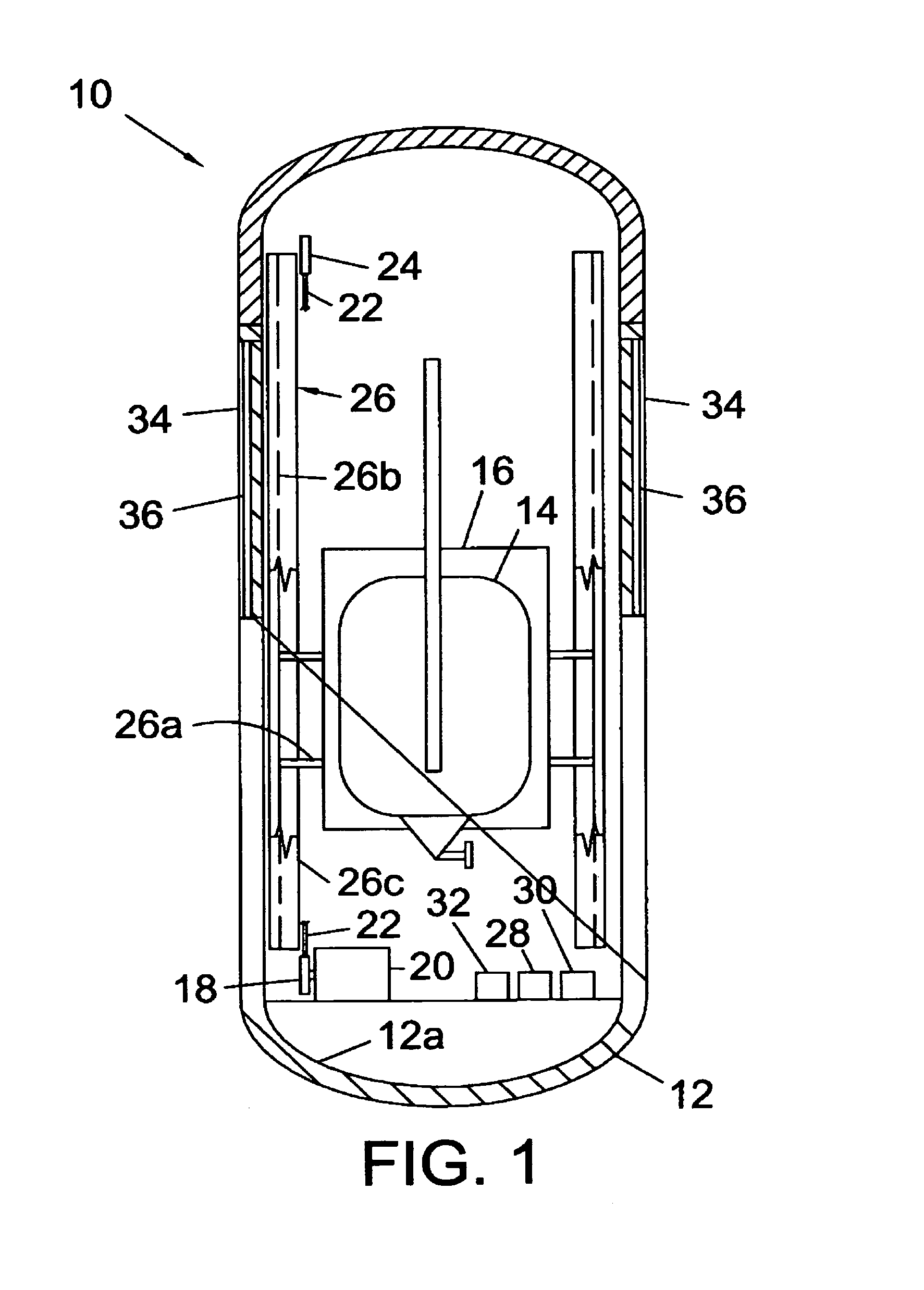
[0013]In one aspect, the system includes guide means to maintain the interior orientation of the cradle and UAV during movement of the UAV within the capsule. The guide means can include one or more rails fixed within the capsule and one or more extensions of the cradle that slidably mate with the guide rail. The guide means can include bearings, such as linear bearings, to facilitate the sliding movement between the extension and the rail.

Problems solved by technology

Some slower speed UAV systems have disadvantages and / or limitations.
Thus, once released from the underwater platform, one commonly used launcher does not allow for a time-delayed launch of the UAV, which can compromise or reveal the position of the underwater platform.
This launching mechanism creates a flame or smoke plume, referred to as a “flame datum”, which also compromises the platform location.
Two typically used launchers cannot be launched at submarine test depth or in shallow water due to risks of the capsules striking the hull of the submarine or other underwater platform.

Method used


Image

  • Deployment system and method for subsurface launched unmanned aerial vehicle
  • Deployment system and method for subsurface launched unmanned aerial vehicle
  • Deployment system and method for subsurface launched unmanned aerial vehicle

Examples


Embodiment Construction

[0027]To provide an overall understanding, certain illustrative embodiments will now be described; however, it will be understood by one of ordinary skill in the art that the systems and methods described herein can be adapted and modified to provide systems and methods for other suitable applications and that other additions and modifications can be made without departing from the scope of the systems and methods described herein.

[0028]Unless otherwise specified, the illustrated embodiments can be understood as providing exemplary features of varying detail, and therefore, unless otherwise specified, features, components, modules, and / or aspects of the illustrations can be otherwise combined, separated, interchanged, and / or rearranged without departing from the disclosed systems or methods. Additionally, the shapes and sizes of components are also exemplary and unless otherwise specified, can be altered without affecting the disclosed systems or methods.

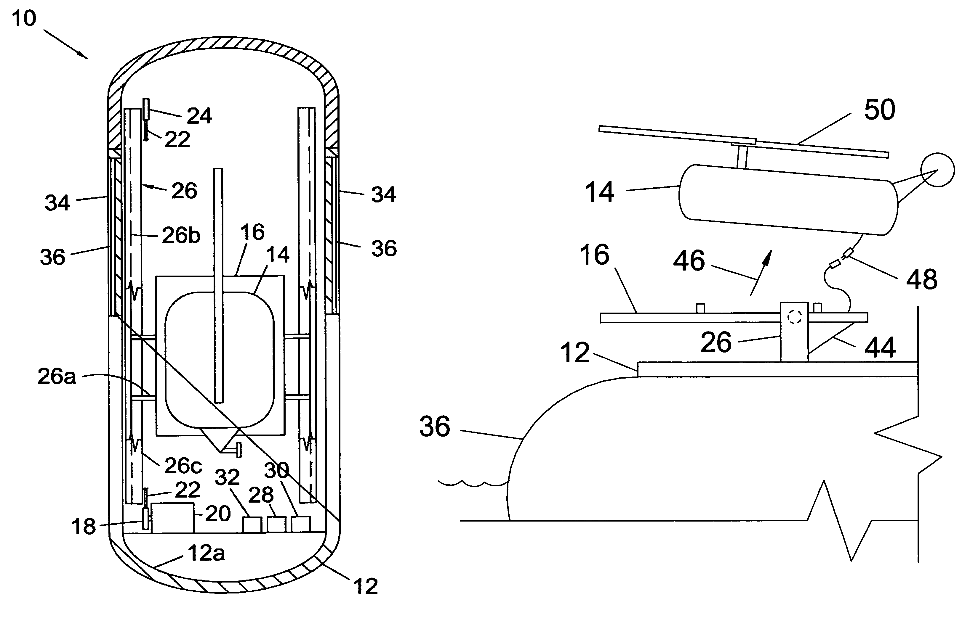
[0029]Referring to FIG. 1, t...


PUM


Abstract

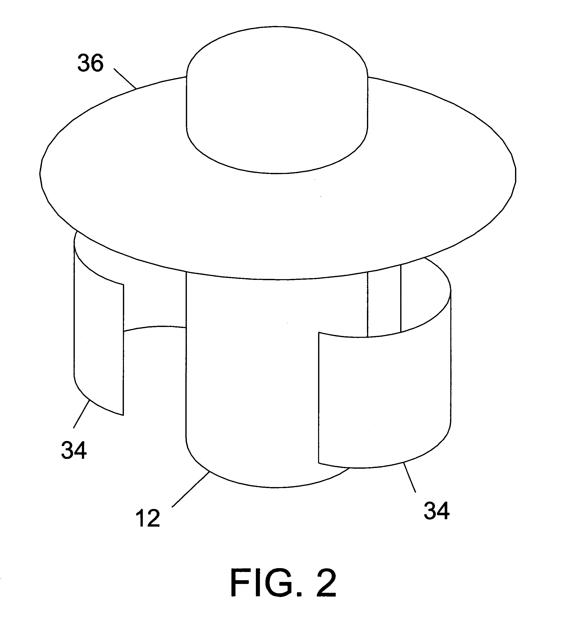
A launch system in which an unmanned aerial vehicle is secured to a platform in a watertight tube adapted to be launched from a submerged platform. Once launched, side panels on the tube are jettisoned and a flotation device is deployed to bring the tube to the surface. The flotation device maintains the tube in a vertical position when rising to and at the surface. After surfacing, a top-sealing cap of the tube is opened. A lifting mechanism within the tube raises the vertically oriented platform assembly up within the tube. Guide rails maintain the vertical orientation of the assembly during lifting. At the topmost point of travel, the assembly is raised clear of the tube and is disengaged from the guide rails, allowing the assembly to pivot about its attachment to the lifting mechanism and assume an orientation favorable for launching the UAV.

Description

STATEMENT OF GOVERNMENT INTEREST[0001]The invention described herein may be manufactured and used by or for the Government of the United States of America for Governmental purposes without the payment of any royalty thereon or therefore.BACKGROUND OF THE INVENTION[0002](1) Field of the Invention[0003]The present invention relates to subsurface launched unmanned aerial vehicles (UAVs) and is directed more particularly to a deployment system for launching a vertical take off and landing (VTOL) UAV or a fixed-wing UAV.[0004](2) Description of the Prior Art[0005]The launching of UAVs from submarines, or other subsurface platforms, is known in the art, e.g., the launching of cruise missiles and other types of missiles and high-speed vehicles. For some purposes, slower speed UAVs are preferred and launch systems for such UAVs are being developed. Some slower speed UAV systems have disadvantages and / or limitations.[0006]One system relies on buoyancy to provide the UAVs initial upward momen...

Claims


Application Information

Patent Timeline
Patent Type & Authority Patents(United States)
IPC IPC(8): B64F1/04F41F3/00F41F3/04
CPCB63G8/28F41F3/07B64F1/04B64C2201/084B64C2201/205B64U70/70B64U80/84
Inventor HEASTON, JEREMY R.TOTH, DAVID E.
Owner NAVAL UNDERSEA WARFARE CENT THE UNITED STATES OF AMERICA
Learn More