Device for reducing the impact for pedestrians
a technology for pedestrians and devices, applied in pedestrian/occupant safety arrangements, braking systems, tractors, etc., can solve the problems of actuators adding to the complexity of the system and the assembly of the vehicle, and every extra component will also take up spa
- Summary
- Abstract
- Description
- Claims
- Application Information
AI Technical Summary
Benefits of technology
Problems solved by technology
Method used
Image
Examples
first embodiment
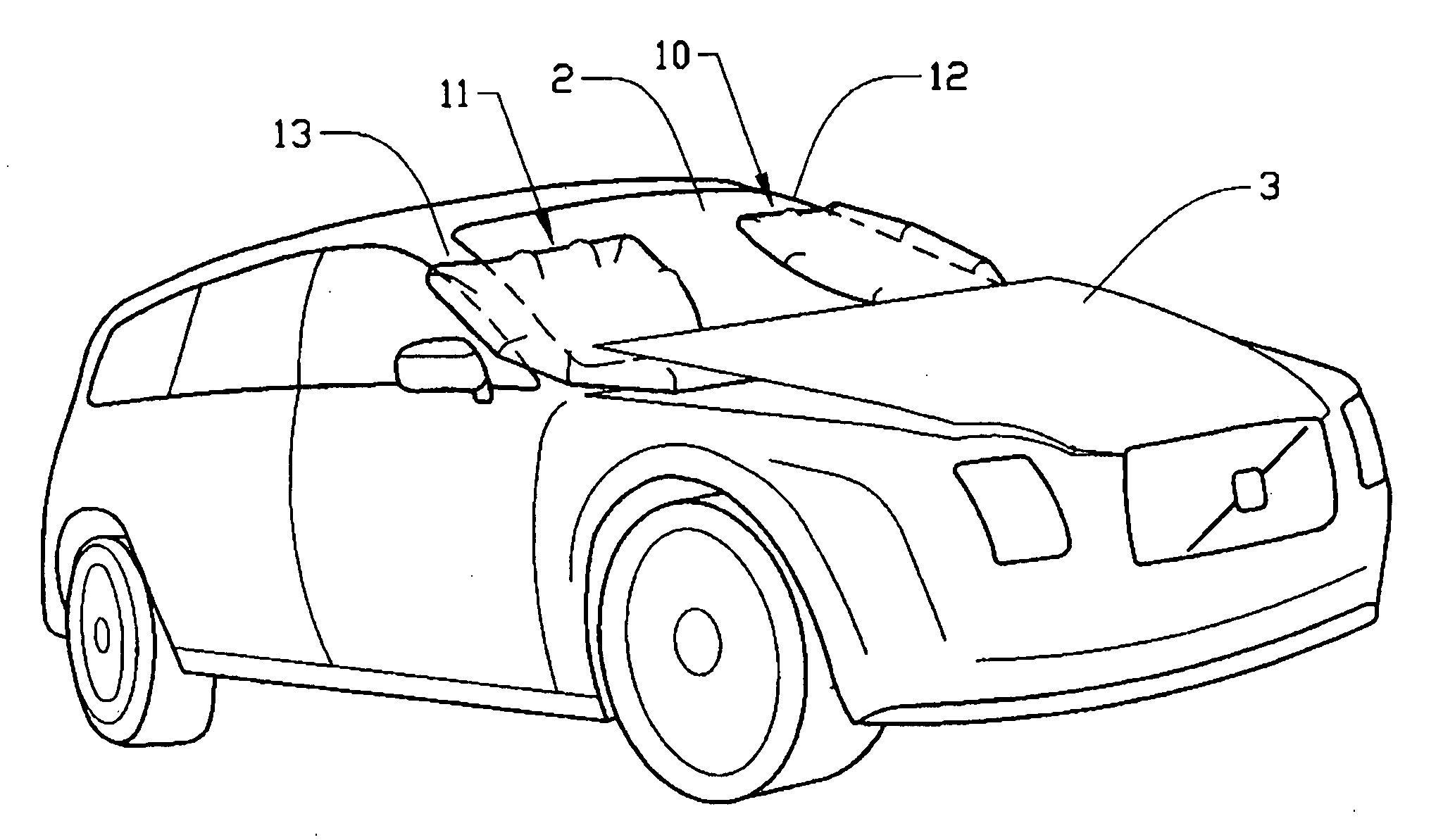
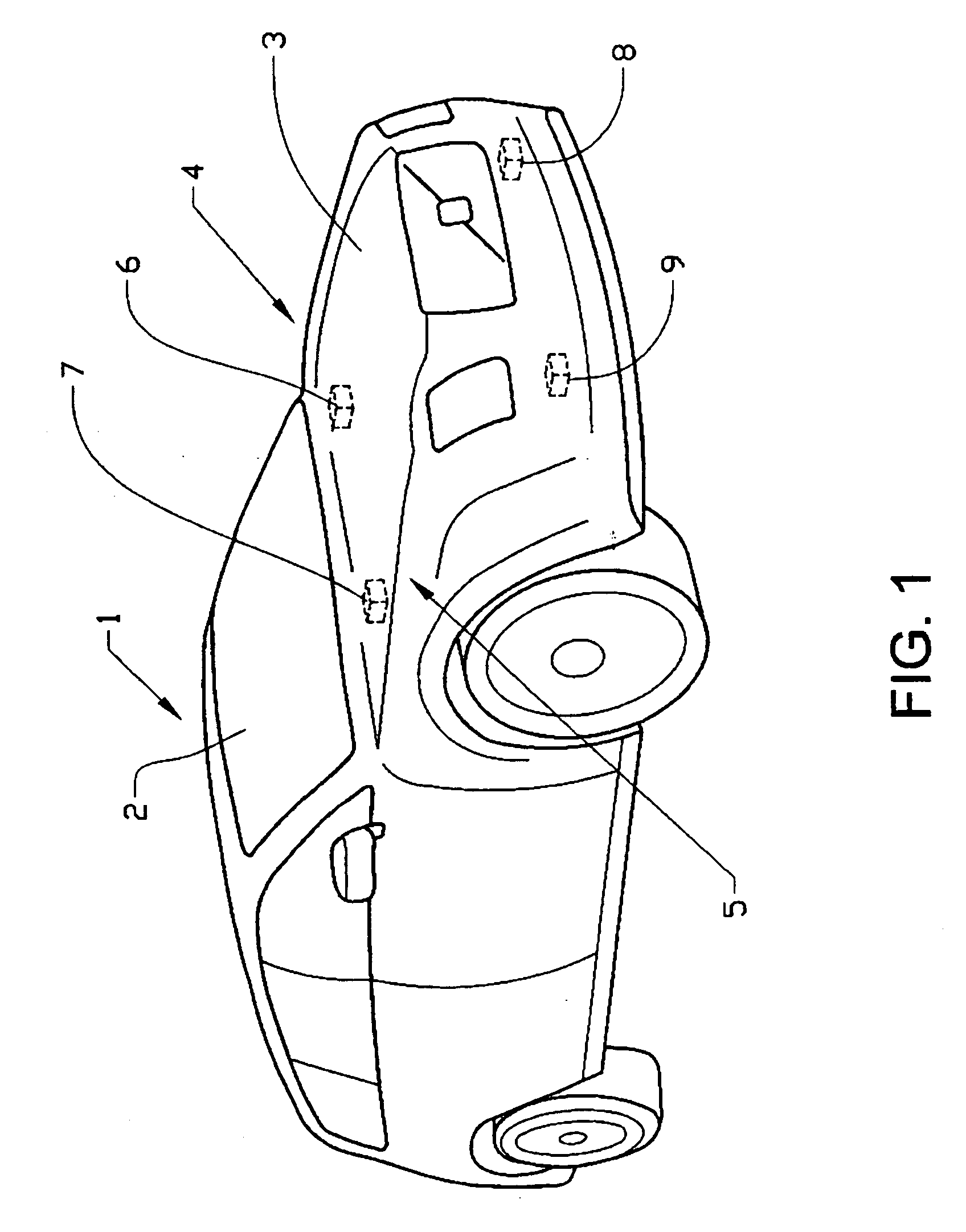
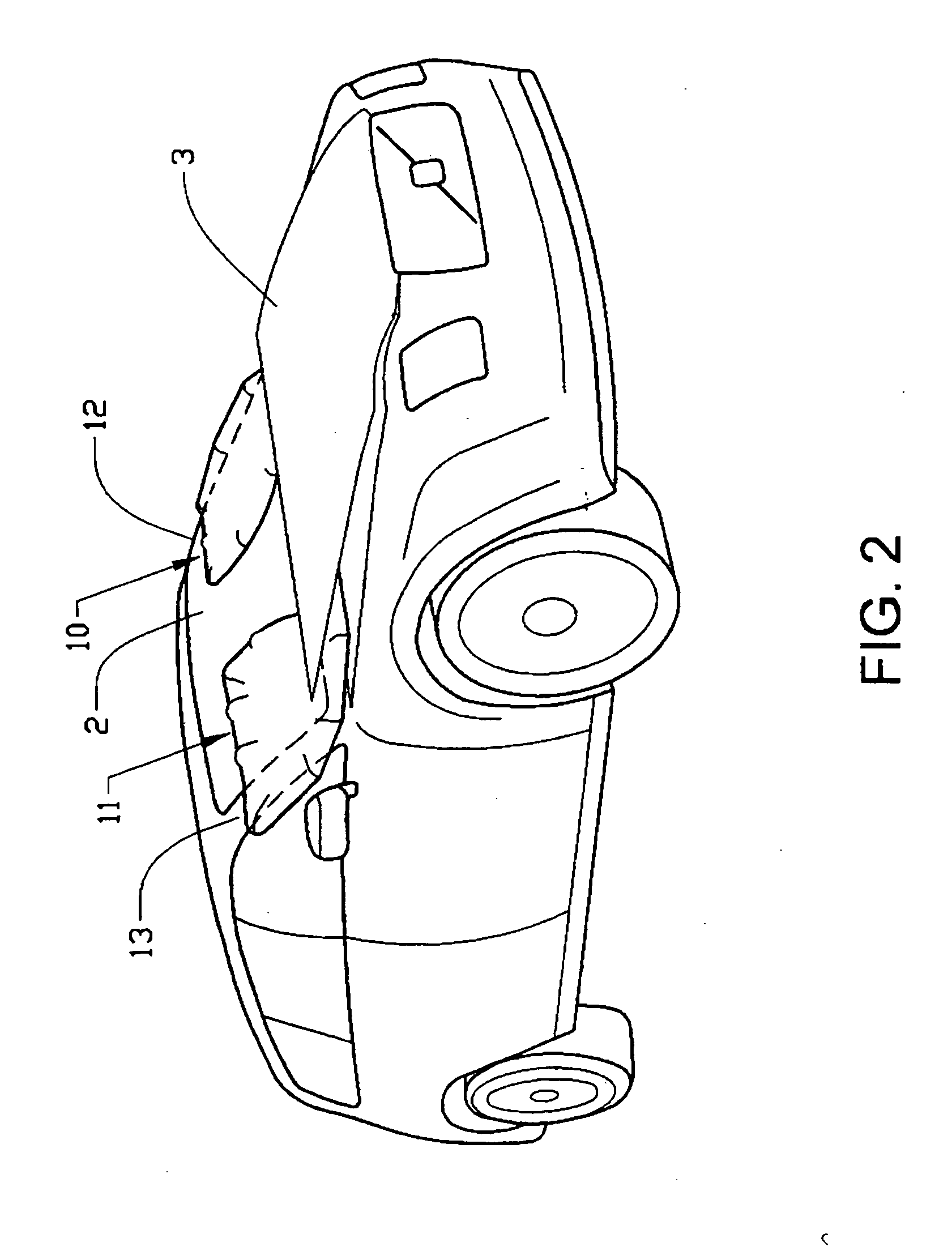
[0038]FIG. 3 shows a schematic a cross-sectional side view of the impact reducing device according to the invention. The figure shows a cross-section through the rear section hood 3 adjacent its side edge. The hood is shown in its normal, closed position. The windshield 2 slopes down towards the front of the vehicle, located to the left in the figure, whereby a scuttle area 14 that extends towards the front of the vehicle, from the lower edge of the windscreen 2 in underneath the hood 3. The basic components of the device include an air bag module 6 that is mounted onto a bracket 15. The airbag module 6 is provided with substantially horizontally extending guide pins 16 on opposite sides of said module, which guide pins 16 located in corresponding slots 17 in the bracket 15. The hood 3 is provided with a hinge system 18 between the rear section of the hood and the scuttle area. The hinge system 18 allows the hood 3 to be opened by releasing and lifting the hood from the front end of...
second embodiment
[0045]FIG. 5 shows a schematic a cross-sectional side view of the impact reducing device according to the invention. The figure shows a cross-section through the rear section hood 3 adjacent its side edge. As in the embodiment of FIG. 3, the vehicle is provided with a windshield 2, a hood 3 and a scuttle area 14 extending towards the front of the vehicle, from the lower edge of the windscreen in underneath the hood. Similarly, an airbag module 6 is provided with substantially horizontally extending guide pins 16 on opposite sides of said module, which guide pins 16 located in corresponding slots 17 in a bracket 15. The hood 3 is provided with an alternative hinge system 25 between the rear section of the hood and the scuttle area. The hinge system 25 allows the hood 3 to be opened by releasing and lifting the hood from the front end of the vehicle, while the hood pivots around said hinge system. The hinge system 25 comprises a linkage having three pivoting joints 26, 27, 28 connecte...
third embodiment
[0050] the shape of an inner panel profile under the rear section of the hood 3 may be adjusted to achieve an optimum combination of air bag deployment resistance. This is done to increase the air bag module reaction force and to achieve a predetermined degree of hood lift due to the air bag expansion.
[0051]FIG. 7 shows a device as described in connection with FIGS. 3 and 4 above, using the reference numerals of these figures. As schematically indicated in FIG. 7, the rear section of the hood 3 to the rear of the airbag module 6 has an inner panel 32 located in a plane at an angle β1 relative to a horizontal plane. Similarly, the scuttle area 14 to the rear of the airbag module 6 is located in a plane at an angle 2 relative to a horizontal plane. FIG. 7 shows an airbag 10 in an initial stage of deployment, while the airbag has begun to inflate (see arrows A7) but before the airbag module 6 has been released from its shear pin. In the embodiment shown in FIGS. 3 and 4 the airbag wou...
PUM
 Abstract
Description
Claims
Application Information
 - R&D
- Intellectual Property
- Life Sciences
- Materials
- Tech Scout
- Unparalleled Data Quality
- Higher Quality Content
- 60% Fewer Hallucinations
Browse by: Latest US Patents, China's latest patents, Technical Efficacy Thesaurus, Application Domain, Technology Topic, Popular Technical Reports.
© 2025 PatSnap. All rights reserved.Legal|Privacy policy|Modern Slavery Act Transparency Statement|Sitemap|About US| Contact US: help@patsnap.com


