Efficient application deployment on dynamic clusters

a dynamic cluster and application technology, applied in the field of clustered computer systems, can solve the problems of time-consuming process of bringing up a new node into an existing cluster, too time-consuming to be practical, and content management becomes difficult, so as to reduce the number of new applications in a node and speed up the deployment of new nodes in a cluster

Inactive Publication Date: 2005-06-23
IBM CORP
View PDF2 Cites 28 Cited by
  • Summary
  • Abstract
  • Description
  • Claims
  • Application Information

AI Technical Summary

Benefits of technology

[0010] It is a primary advantage of some aspects of the present invention that the speed of deployment of new nodes in a cluster, and new applications in a node is reduced, compared to disk cloning times.

Problems solved by technology

The process of bringing up a new node into an existing cluster is time consuming.
However in the dynamic environment of web server applications, this is too time consuming to be practical.
This requirement has a serious drawback, as content management then becomes difficult, requiring the maintenance of many copies of the same data to assure coherence of data.
However, this technique is effective only for applications that do not use any files located outside application-specific directories.
Such applications would require multiple symbolic links, which would be cumbersome and time consuming to establish.
Creating such a directory on a shared file system is problematic, since different instances of the application will overwrite its files.

Method used


Image

  • Efficient application deployment on dynamic clusters
  • Efficient application deployment on dynamic clusters
  • Efficient application deployment on dynamic clusters

Examples


example 1

[0127] Example 1 illustrates an installation of the above noted Apache Web Server using the technique outlined in Listing 1. The configuration file is shown in Listing 2. The directory structure on the volume / remote / filesystem1 / Apache is shown in Listing 3.

Listing 2# My Apache Site / / remote / filesysteml / Apache /   mklink / remote / serverl / Apache / addMimeTypes.sh / home / httpd / remote / filesystem2 / WebPages / mklink / var - mktree

[0128]

Listing 3 / etc / etc / httpd / / etc / httpd / conf / etc / logrotate.d / home / home / httpd / cgi-bin / home / httpd / html / home / httpd / icons / usr / usr / bin / usr / lib / usr / lib / apache / usr / man / usr / man / man1 / usr / man / man8 / usr / sbin / var / var / cache / httpd / van / log / van / log / httpd

[0129] The mapping algorithm will first mark the directory / var as a mktree directory. The significance of this designation is that any directories on the remote file systems that map to the directory / var will be created. There is no linking between such mapped directories to the remote file system.

[0130] Next, the algorithm will wal...

example 2

[0141] Example 2 involves the installation of some Perl CGls along with the Apache Web Server. The configuration file is shown in Listing 8.

Listing 8# My CGI Enhanced Apache Site / / remote / filesysteml / Apache / mklink   / remote / filesysteml / Apache / addMimeTypes.sh / home / httpd / remute / filesystem2 / Webpages / mklink / var - mktree / home / httpd / remote / filesystem3 / PerlCGIs / mklink   / remote / filesystem3 / PerlCGIs / reconfigureApache.sh

[0142] This example enhances Example 1 by adding PerlCGI files, which install in the directory / home / httpd / cgi-bin, and update the Apache config files to include support for PerlCGIs.

[0143] In Example 1, the directory / home / httpd / html was created because of the second entry in the configuration file (Listing 2). In this example, the link / home / httpd / cgi-bin will be removed, and instead all the files and directories in the directory / remote / filesysteml / Apache / home / httpd / cgi-bin will be linked to from the a newly created directory / home / httpd / cgi-bin. Then, all the files ...


PUM


Abstract

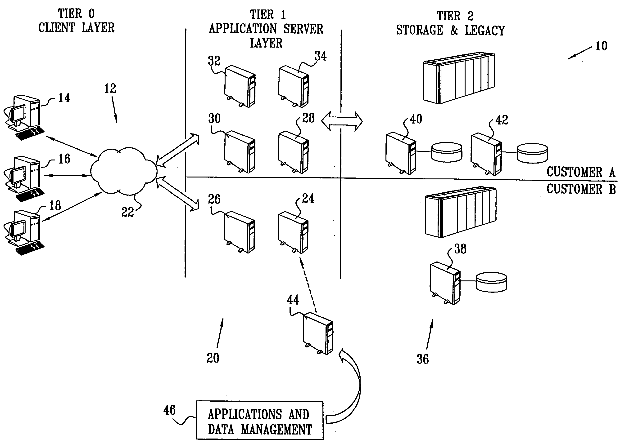
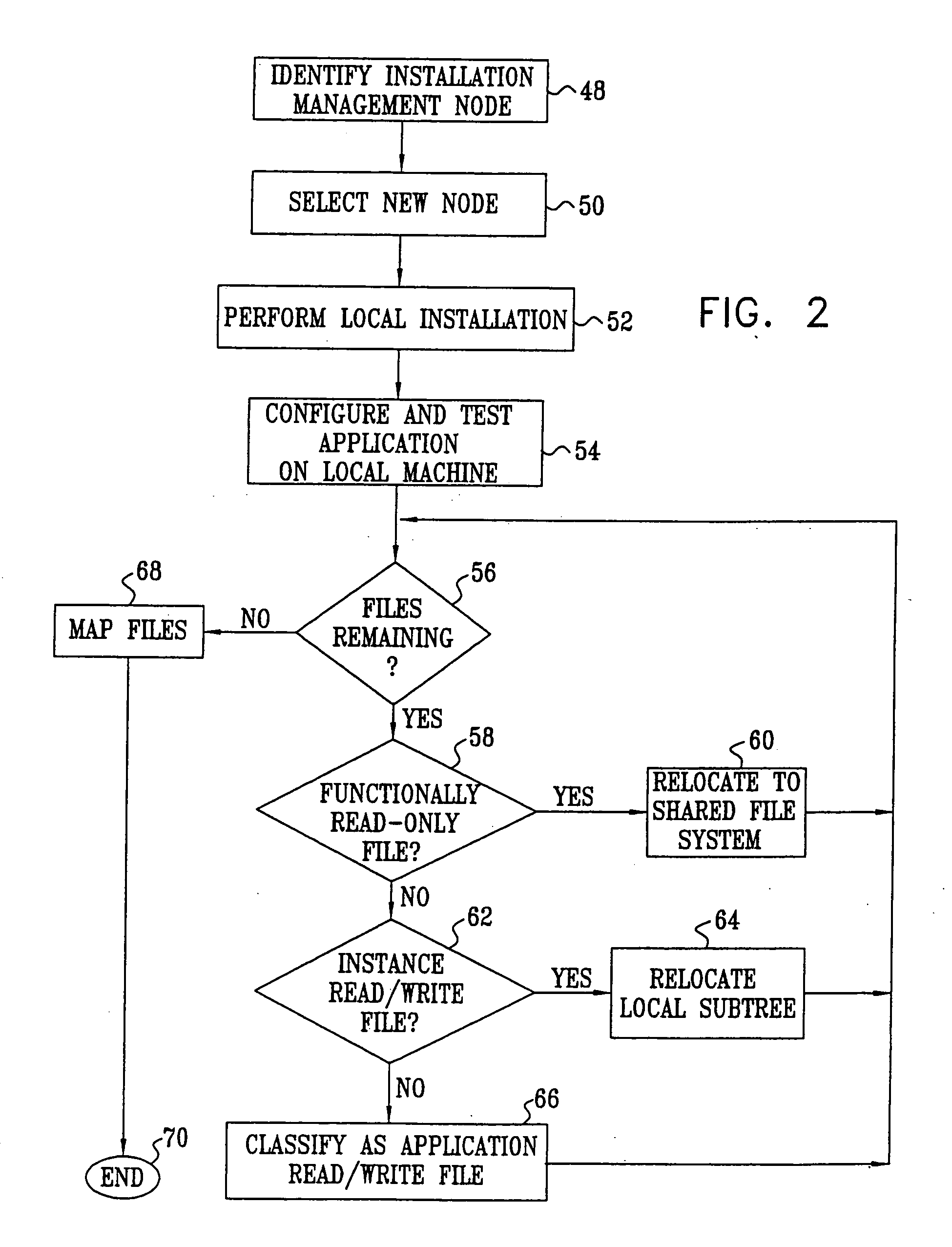
A cluster application deployment model provides an efficient computer implemented technique for the deployment of applications on a shared file system, and includes an automated mechanism for mapping the shared application image into the local file system of a new node of a cluster.

Description

CROSS-REFERENCE TO RELATED APPLICATIONS [0001] This is a divisional of copending parent application Ser. No. 10 / 044,161, filed Jan. 7, 2002, which claims the benefit of provisional application No. 60 / 260,330, filed Jan. 8, 2001.BACKGROUND OF THE INVENTION [0002] 1. Field of the Invention [0003] This invention relates to clustered computer systems. More particularly, this invention relates to efficiencies in the deployment of applications on a new node of a cluster. [0004] 2. Description of the Related Art [0005] Cluster technology now supports computer system availability, and has become indispensable to large business operations. A cluster is a collection of one or more complete systems that cooperate to provide a single, unified computing capability. Typically, the cluster members are interconnected by a data network, such as an IP network. From the perspective of the end user, the cluster operates as though it were a single system. Clusters provide redundancy, such that any singl...

Claims


Application Information

Patent Timeline
Patent Type & Authority Applications(United States)
IPC IPC(8): G06F9/445
CPCG06F8/61Y10S707/99955Y10S707/99953
Inventor AZAGURY, ALAINKOREN, YAIRROCHWERGER, BENNYTAL, ARIE
Owner IBM CORP
Why Eureka
Try Eureka