Panel cover attachments to snap together connectors

a technology of connectors and panel covers, applied in the direction of dismountable cabinets, couplings, sectional furniture, etc., to achieve the effect of stabilizing the structur

Inactive Publication Date: 2009-01-06
CUBE CONCEPTS LLC
View PDF48 Cites 29 Cited by
  • Summary
  • Abstract
  • Description
  • Claims
  • Application Information

AI Technical Summary

Benefits of technology

[0010]Panels, structural elements and / or design elements snap together, at an edge, forming a substantially right angle. Additional panels and / or structural elements, design elements or other connectable elements may be added to form other structures. An alignment stop may be added to prevent sliding between a latch and a catch which may cause misalignment. At or near the corners, or near the edges on the panel or other element a buttress can be formed. Two adjacent buttresses can support each other and act as a larger support which can further stabilize the structure.

Problems solved by technology

A remaining challenge in the field of snap together elements or panels is to attach the snap together attachments on panels and non-panels.
An additional challenge is to form snap together 5 or 6 sided structural elements and structures.

Method used


Image

  • Panel cover attachments to snap together connectors
  • Panel cover attachments to snap together connectors
  • Panel cover attachments to snap together connectors

Examples


Embodiment Construction

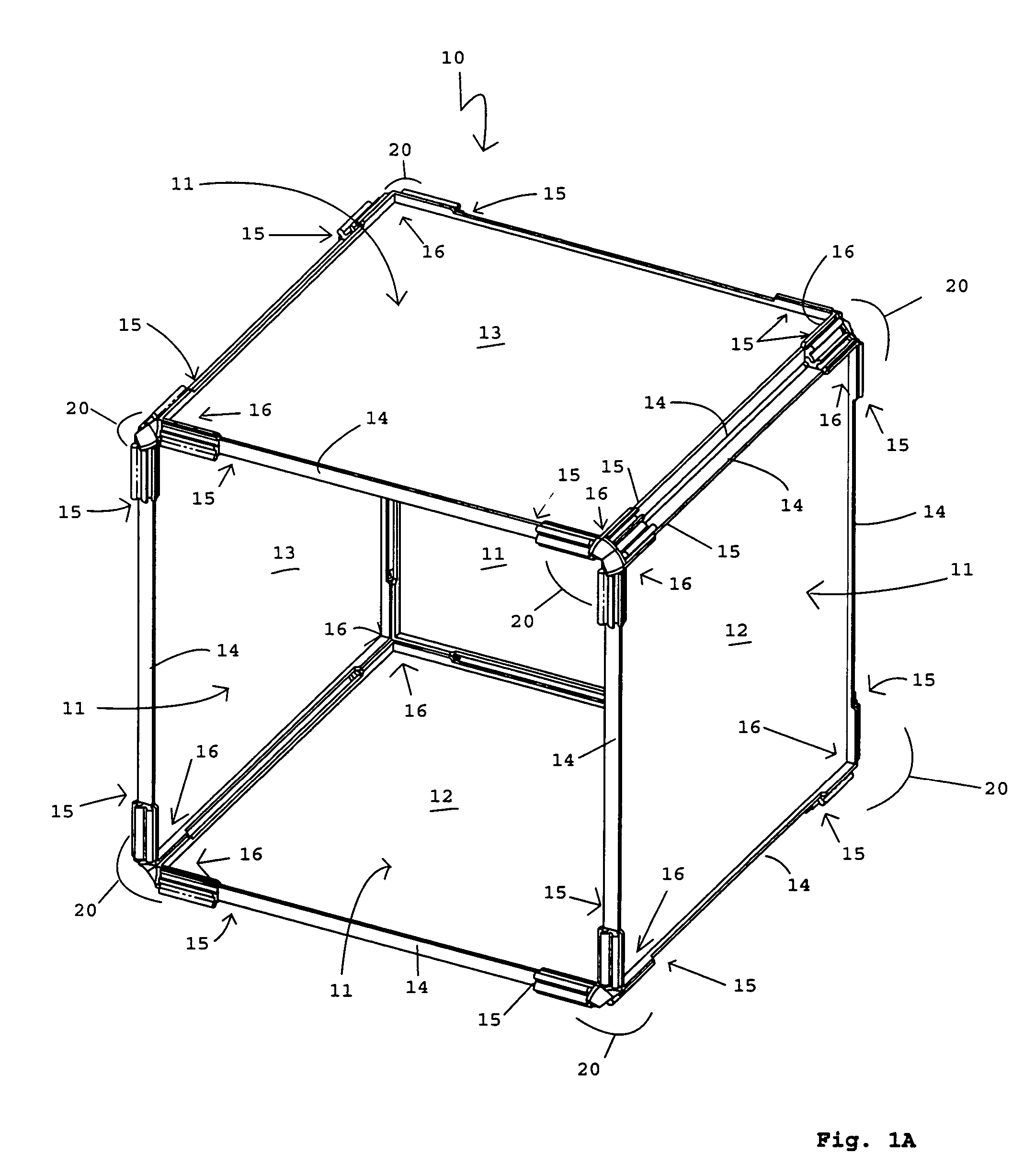
[0060]Shown in FIG. 1A is a front perspective view of a preferred embodiment, generally designated 10.

[0061]The cube is formed of five four sided panels 11. Each panel has a front 12 and a back side 13 face and an edge 14 at each side. At each end 15, of each edge 14, near the corners 16 of each panel 11, a latch / catch pair 20 is formed. Viewed from the edge 14, a latch 21 and a catch 22 are formed near the corner 16. The latch / catch pairs 20 are reversed such that on any given edge 15 of a panel 11 one latch 21 will be exposed on ore side and one catch 22 will be exposed on the other side. This configuration allows alternating panels to be used to construct the entire structure.

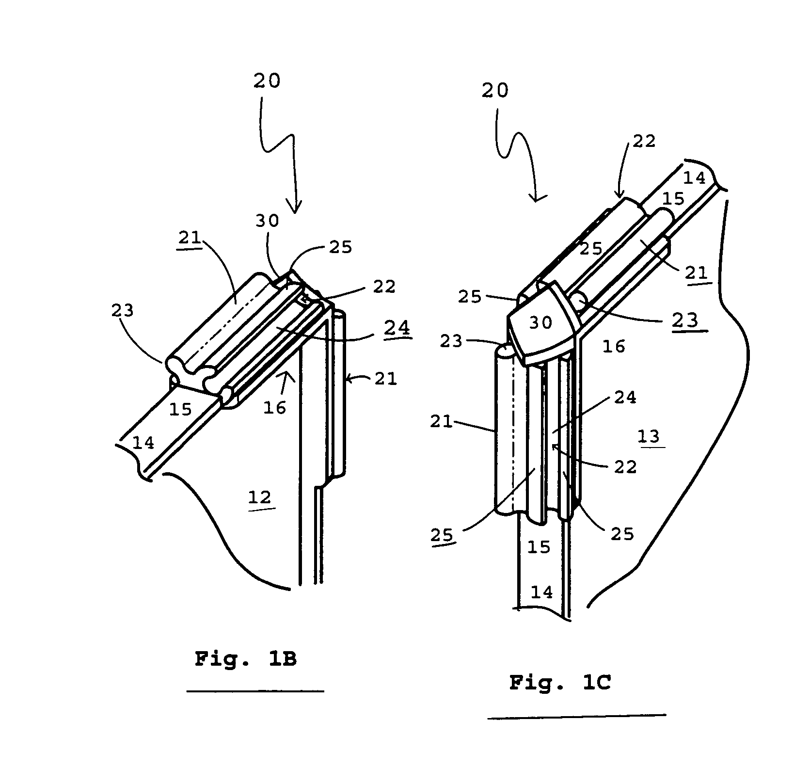
[0062]Shown in FIGS. 1B, 1C, 1D and 1E are front and rear perspective views of a corner of an unattached panel, a perspective view of an attached front corner and a cut away view of FIG. 1D at line A-A.

[0063]In FIGS. 1B & 1C the latches 21 shape is shown, the tab projection forming the latch is elongated wit...


PUM

PropertyMeasurementUnit
angleaaaaaaaaaa
angleaaaaaaaaaa
elasticityaaaaaaaaaa

Abstract

Attachments to affix panel covers, with snap together latches and / or catches to elements such as rods or panels and thereby attaching the rods and / or panels to each other to form structures.

Description

RELATED APPLICATIONS[0001]This application is a Continuation In Part of U.S. application Ser. No. 10 / 271,836, filed Oct. 15, 2002 entitled “Snap Together Modular Storage”, which is a Continuation In Part of U.S. patent application Ser. No. 09 / 759,898 filed Jan. 13, 2001 entitled Snap Together Modular Storage now U.S. Pat. No. 6,557,955, from which PCT application PCT / US02 / 00946, filed Jan. 11, 2002 entitled “Assemble-In-Place Modular Storage” derives, each of which are hereby incorporated by this reference.BACKGROUND OF THE INVENTION[0002]1. Field of the Invention:[0003]This present invention relates to a novel assembly device and system. More specifically, to a snap-together method and device whereby panels or other elements with interlocking latches and catches are connected.[0004]2. Related Art:[0005]Modular storage systems are useful to allow a user to customize a component system to fit his or her particular needs. Panel type storage whereby similar side panels are connected vi...

Claims


Application Information

Patent Timeline
Patent Type & Authority Patents(United States)
IPC IPC(8): F16B12/00A47B47/04B65DF16B12/26F16B12/46
CPCA47B47/0033A47B47/042F16B12/46F16B12/26Y10T403/73Y10T403/7094F16B2200/30F16B2200/67
Inventor SARAVIS, DARREN
Owner CUBE CONCEPTS LLC
Why Eureka
Try Eureka