Intervertebral implant with joint parts mounted on roller bodies

a technology of intervertebral implants and roller bodies, which is applied in the field of intervertebral implants, can solve the problems of pain for patients, wear on the surface, abrasion and resistance, etc., and achieve the effect of facilitating the insertion into the intervertebral spa

Inactive Publication Date: 2009-01-06
SYNTHES USA
View PDF10 Cites 244 Cited by
  • Summary
  • Abstract
  • Description
  • Claims
  • Application Information

AI Technical Summary

Benefits of technology

[0030]C) release and removal of the device inserted into the intervertebral implant for blocking the joint(s). Blocking the joint provides the advantage that the moveable sections with the external apposition surfaces can be inserted more easily into the intervertebral space to be treated.
[0031]In a further application of the process according to the invention, this comprises the subsequent blocking of the joint(s) on the implanted intervertebral implant by means of the device intended for blocking the joint(s). Th

Problems solved by technology

The disadvantages of this known intervertebral disk endoprosthesis is thata) the arrangement of an intervertebral disk endoprosthesis with only one fulcrum does not take sufficient account of the overlaying swivel movements transferred by the natural intervertebral disk, specifically in the case of anterior-posterior and in lateral flexion, which in the natural intervertebral disk are independent of each other;b) the verterbral joint is put under strain by swivel movements, specifically with translation in the anterior-posterior direction (face joint), which could cause pain f

Method used


Image

  • Intervertebral implant with joint parts mounted on roller bodies
  • Intervertebral implant with joint parts mounted on roller bodies
  • Intervertebral implant with joint parts mounted on roller bodies

Examples


Embodiment Construction

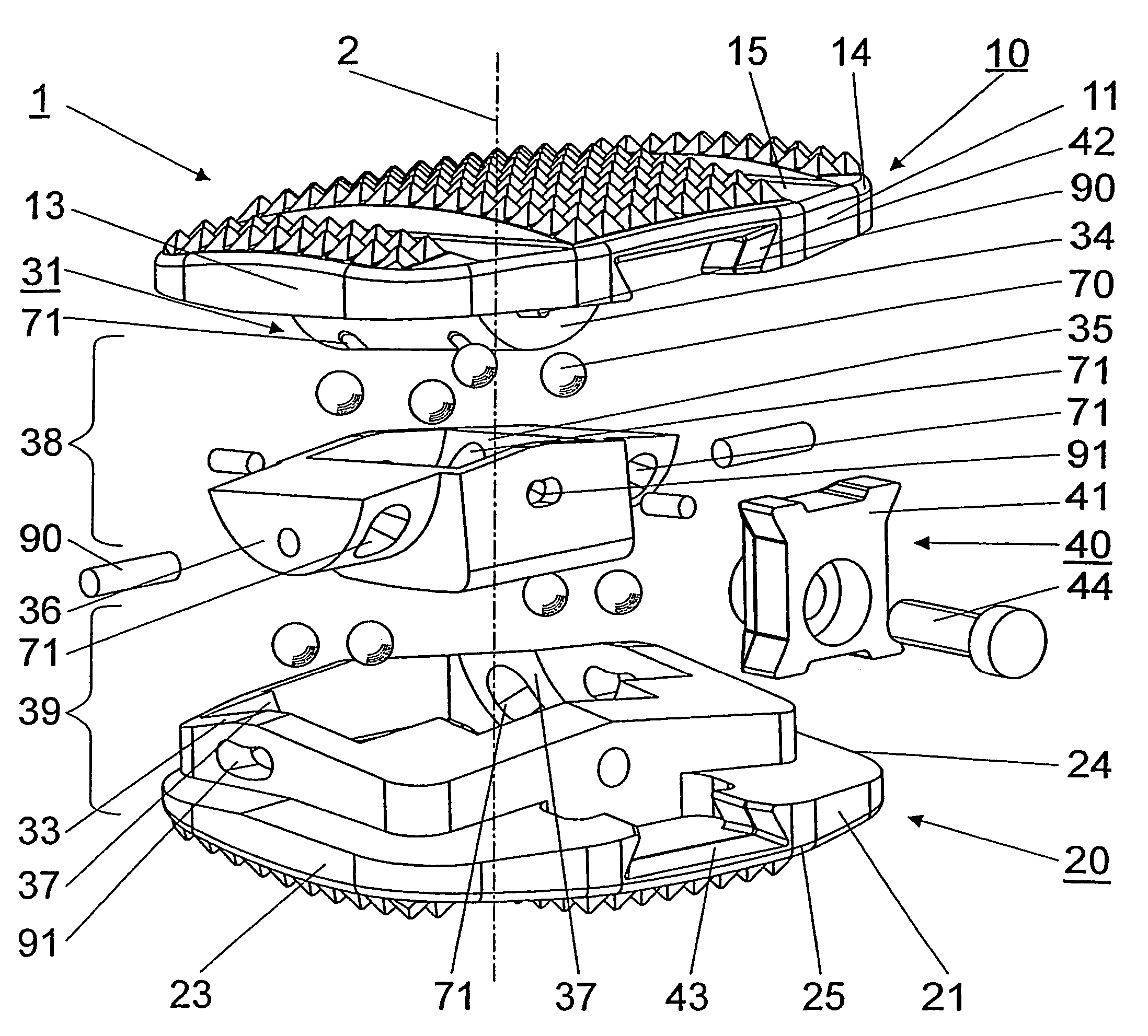
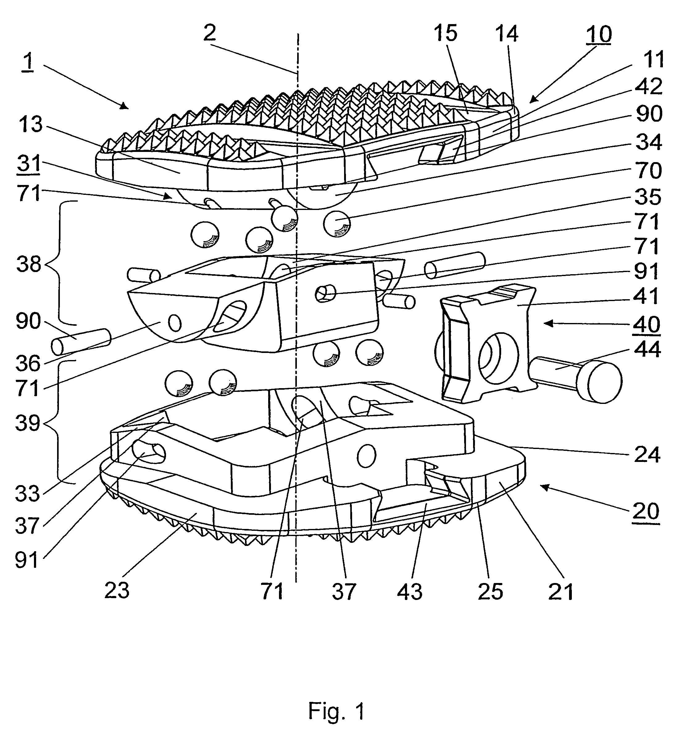
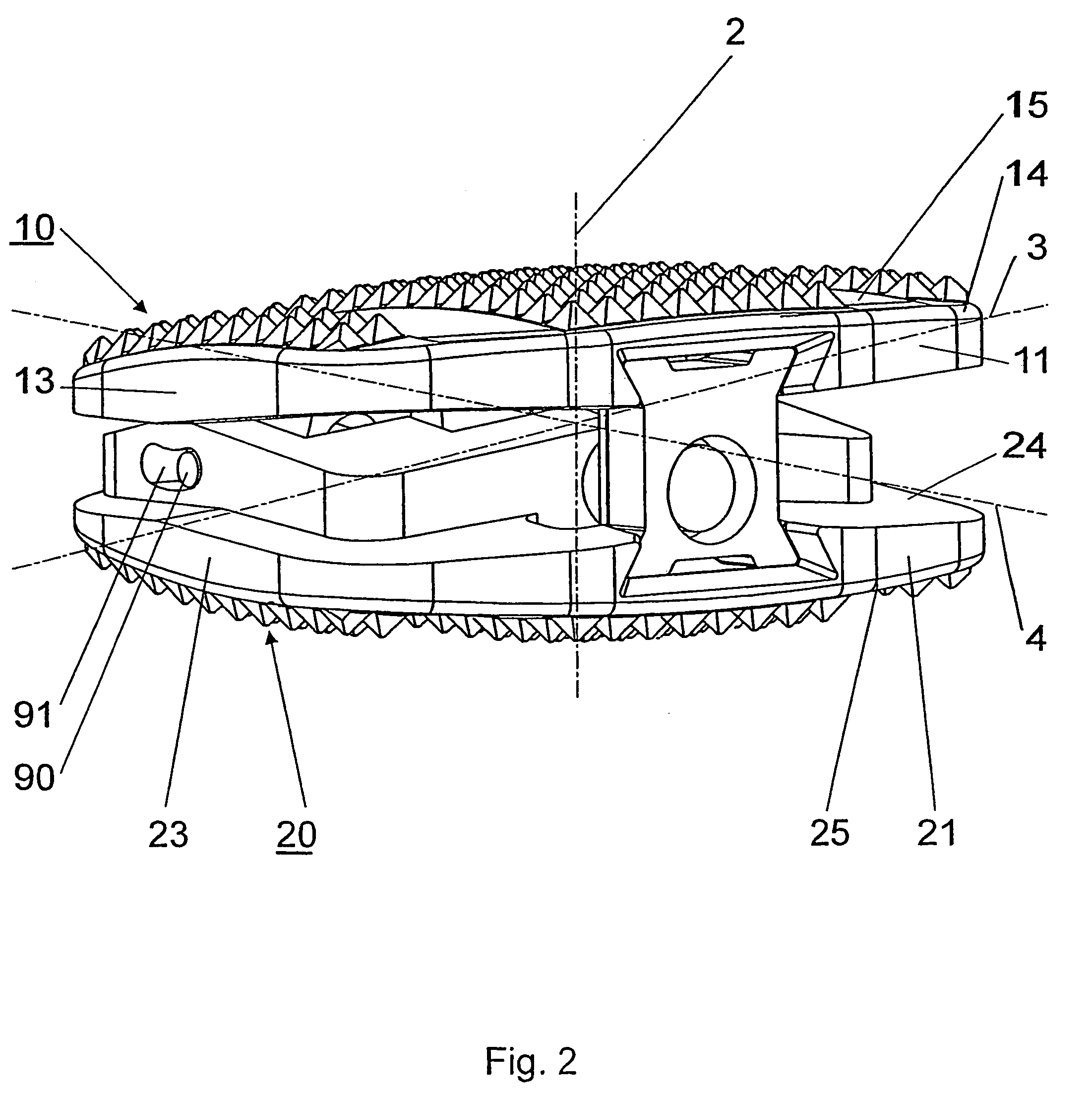
[0037]FIG. 1 and FIG. 2 show an embodiment of the intervertebral implant 1 according to the invention, which comprises an upper section 10 with a top apposition surface 15 arranged perpendicular to the central axis 2 for laying on the base plate of an adjoining vertebral body, a lower section 20 with a lower apposition surface 25 arranged perpendicular to the central axis 2 for laying on the cover plate of the adjoining vertebral body and two joints 38;39. The upper section 10 and the lower section 20 are connected with the joints 38;39 and moveable in relation to each other, whereby the mobility of the upper section 10 relative to the lower section 20 is restricted by a first swivel axle 3 arranged perpendicular to the central axis 2 within an angle range of +10° to −6° and by a second swivel axle 4 arranged perpendicular to the central axis 2 and vertical to the first swivel axle 3 within an angle range of ±7°.

[0038]The two joints 38;39 are realised by three joint elements 31;32;3...


PUM


Abstract

An intervertebral implant (1), including an upper section (10) provided with a ventral side area (11), a dorsal side area (12), two lateral side areas (13,14), a top apposition surface (15) and a bottom surface (16), a lower section (20) provided with a ventral side area (21), a dorsal side area (22), two lateral side areas (23,24), a bottom apposition surface (25) and a top surface (26), wherein the two sections (10,20) are moveable in relation to each other by means of two joints (38;39) arranged between the two sections (10;20), and wherein each of the joints (38;39) has a swivel axle (3;4) and the two swivel axles (3;4) are arranged perpendicular to each other, each of the joints (38;39) comprises at least one axle (34;36) coaxial to the relevant swivel axle (3;4) and a bearing shell (35;37) receiving the axle (34;36), and roll bodies (70) are inserted between the axles (34;36) and the bearing shells (35;37).

Description

[0001]English translation of the International Patent Application No. PCT / CH02 / 00704 “Zwischenwirbelimplantat mit auf Wälzkörpern gelagerten Gelenkteilen”im Namber der Mathys Medizinaltechnik AGBACKGROUND OF THE INVENTION[0002]The invention relates to an intervertebral implant according to the generic term of Patent Claim 1 and to a process for the replacement of a defect, natural intervertebral disk by an intervertebral implant.[0003]After removal of a damaged, natural intervertebral disk or a damaged nucleus pulposus of an intervertebral disk, implants or prostheses are inserted into the intervertebral space of two neighbouring vertebral bodies. This suggests the idea of restoring the situation as much as possible to a natural state, i.e. specifically to restore the original height of the intervertebral disk and thus the original distance between the two neighbouring vertebral bodies. Furthermore, the patient should be able to carry out movements of the neighbouring vertebral bodi...

Claims


Application Information

Patent Timeline
IPC IPC(8): A61F2/44A61B17/86A61F2/00A61F2/30A61F2/46
CPCA61F2/4425A61B17/86A61B17/863A61F2/4455A61F2002/30365A61F2002/30387A61F2002/30393A61F2002/30492A61F2002/30507A61F2002/30515A61F2002/30517A61F2002/30528A61F2002/30604A61F2002/30632A61F2002/30634A61F2002/3064A61F2002/30644A61F2002/30774A61F2002/30785A61F2002/30787A61F2002/30794A61F2002/30843A61F2002/443A61F2002/4635A61F2220/0025A61F2220/0033A61F2002/30639A61F2002/3079
Inventor AEBI, MAXBURKARD, DOMINIQUEFRIGG, ROBERTLECHMANN, BEATMATHYS, JR., ROBERTPAVLOV, PAUL
Owner SYNTHES USA
Why Eureka
Try Eureka