Surface light source device and backlight unit having the same

a technology of surface light source and backlight unit, which is applied in the direction of point-like light source, lighting and heating apparatus, instruments, etc., can solve the problems of color stains still appearing at corners of the board, color stains appearing and high cost without significantly lessening color non-uniformity at the so as to achieve more uniform white light and suppress color stains at side portions of the screen

Inactive Publication Date: 2009-01-13
SAMSUNG ELECTRONICS CO LTD
View PDF4 Cites 11 Cited by
  • Summary
  • Abstract
  • Description
  • Claims
  • Application Information

AI Technical Summary

Benefits of technology

[0013]The present invention has been made to solve the foregoing problems of the prior art and therefore an aspect of the present invention is to provide a high-quality surface light source device capable of suppressing color stains at side portions of the board and producing more uniform white light.
[0014]Another aspect of the invention is to provide a backlight unit equipped with a light source device capable of suppressing color stains and producing more uniform white light.

Problems solved by technology

To reduce color non-uniformity including color stains, a greater number of LEDs may be more densely arranged, which however entails higher costs without considerably lessening color non-uniformity at the side portions of the screen.
However, in the aforesaid LED arrangement, color stains appear at side portions of the board, specifically, upper side portion S1 and lower side portion S3 of the board due to non-uniform color combination and light reflection in the vicinity of the reflective plate 17.
However, such color stains still appear considerably at corners of the board, notably, an upper right corner and a lower left corner.

Method used


Image

  • Surface light source device and backlight unit having the same
  • Surface light source device and backlight unit having the same
  • Surface light source device and backlight unit having the same

Examples


Embodiment Construction

[0037]Exemplary embodiments of the present invention will now be described in detail with reference to the accompanying drawings. This invention may, however, be embodied in many different forms and should not be construed as limited to the embodiments set forth herein. Rather, these embodiments are provided so that this disclosure will be thorough and complete, and will fully convey the scope of the invention to those skilled in the art. In the drawings, the shapes and dimensions may be exaggerated for clarity, and the same reference signs are used to designate the same or similar components throughout.

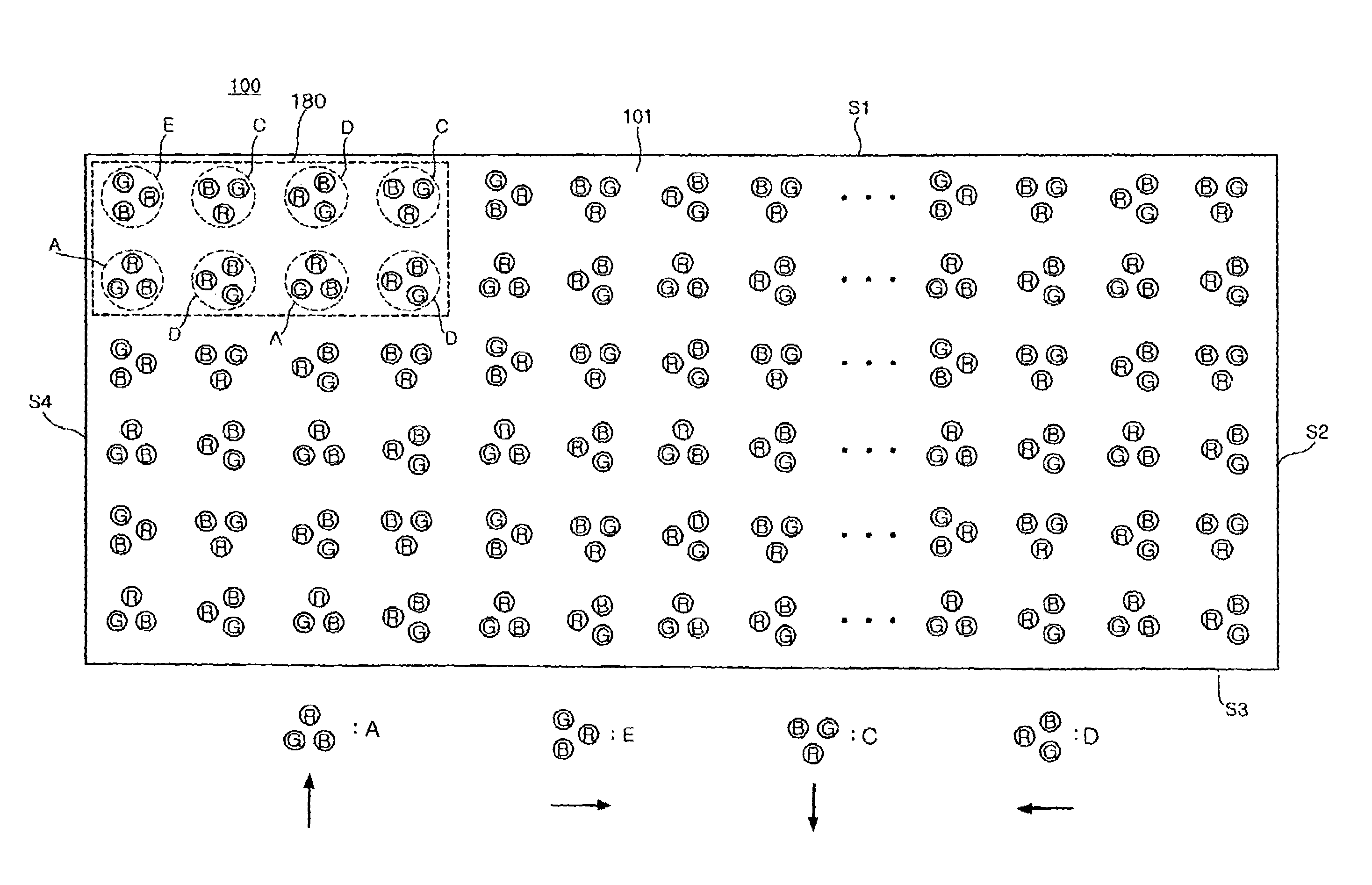
[0038]FIG. 3 is a plan view illustrating a surface light source device according to an embodiment of the invention, and FIG. 4 is a schematic plan view for better understanding of FIG. 3. Referring to FIG. 3, the surface light source device 100 includes a rectangular-shaped board 101 and a plurality of red R, green G and blue B LEDs mounted thereon. A wiring pattern is formed on the ...


PUM


Abstract

A surface light source device having LED clusters arranged in a matrix of rows and columns on a board. Each of the LED clusters includes red, green and blue LEDs arranged in a triangle. The LED clusters are grouped into A, E, C and D, which have the red LEDs located top, right, bottom and left, respectively, from a center of the triangle. The matrix of the LED clusters includes alternating first and second type rows arranged repeatedly from top to bottom of the matrix, terminating with the second type row. The first type rows each have first type cluster arrays of the LED clusters arranged in a repeating order of E, C, D and C from left to right. The second type rows each have second type cluster arrays of the LED clusters arranged in a repeating order of A, D, A and D from left to right.

Description

CLAIM OF PRIORITY[0001]This application claims the benefit of Korean Patent Application No. 2006-69747 filed on Jul. 25, 2006 in the Korean Intellectual Property Office, the disclosure of which is incorporated herein by reference.BACKGROUND OF THE INVENTION[0002]1. Field of the Invention[0003]The present invention relates to a surface light source device, and more particularly, to a high quality, high-uniformity surface light source device using a light emitting diode (LED) and a direct-type backlight unit having the surface light source device.[0004]2. Description of the Related Art[0005]Recently, with a thinner and higher-performing trend of a display device, a liquid crystal display has been broadly utilized in TVs or monitors. A liquid crystal panel does not emit light on its own, thereby requiring a separate light source unit, i.e., a backlight unit (BLU). The BLU has adopted as its light source a cold cathode fluorescent lamp (CCFL), which, however, is giving way to a light em...

Claims


Application Information

Patent Timeline
Patent Type & Authority Patents(United States)
IPC IPC(8): F21V9/00
CPCG02F1/133603G02F2001/133613G02F1/133613G02F1/1335
Inventor KIM, BUM JIN
Owner SAMSUNG ELECTRONICS CO LTD
Why Eureka
Try Eureka