Method and apparatus for collecting a blood component and performing a photopheresis treatment

a technology of blood components and photopheresis, which is applied in the direction of positive displacement liquid engines, multi-stage water/sewage treatment, separation processes, etc., can solve the problems of requiring several hours to treat a patient or obtain a sufficient supply of separated blood fragments, and the system is very complex to manufactur

Active Publication Date: 2009-01-13
MALLINCKRODT HOSPITAL PRODUCTS IP LTD
View PDF295 Cites 101 Cited by
  • Summary
  • Abstract
  • Description
  • Claims
  • Application Information

AI Technical Summary

Benefits of technology

[0013]In another embodiment the cassette comprises a rigid plastic cover having a top surface, a bottom surface, and a wall having a plurality of openings; said rigid plastic base having a top surface, a bottom surface, and a wall having a plurality of openings adapted to overlap with the openings of the wall of the cover; a plurality of first flexible tubings extending out of or entering the housing; a plurality of second flexible tubing secured in a depressed raceway located on the bottom surface of the base, said second flexible tubing are located outside of the housing and extending through or entering the openings of the wall of the base; and a plurality of apertures located on said base section and expose the first flexible tubings inside the housing so that fluid flow through the exposed section can be prevented when external pressure means is exerted on the exposed section through the apertures.
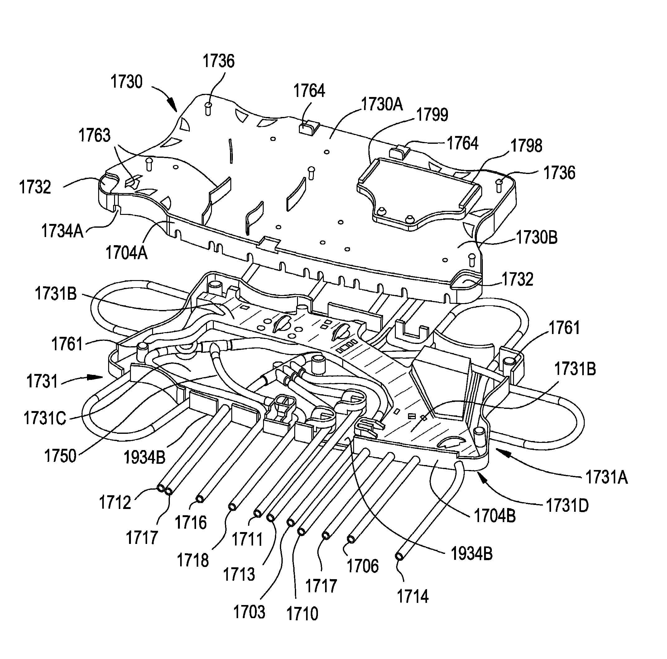
[0014]In another embodiment the invention provides for an apparatus for controlling movement of fluid and separated component of the fluid comprising a cassette having a housing formed by joining a rigid plastic cover and a rigid plastic base; said rigid plastic cover having a top surface, a bottom surface, and a wall having a plurality of openings; said rigid plastic base having a top surface, a bottom surface, and a plurality of apertures through the top and bottom surfaces, and a wall having a plurality of openings adapted to overlap with the openings of the wall of the cover; said top surface of the base comprises a first upper level and a first lower level, wherein the first lower level has a plurality of first flexible tubings, secured by raceways, for one or more of a) connecting to other tubings through multitube connectors, b) extending out of or entering the housing, or c) forming first flexible tube loops having one end extending out of the housing and one end entering the housing; said plurality of apertures are located on the first lower level and expose at least one section of the first flexible tubing inside the housing so that fluid flow through the exposed section can be prevented when external pressure means is exerted on the exposed section through the apertures; and said bottom surface of the base comprise a second upper level and a second lower level, wherein the second lower level has a plurality of second flexible tubing outside of the housing and secured by raceways on said second lower level for one or more of extending through or entering the openings of the wall of the base or forming second flexible tube loops having one end extending out of the wall and one end entering the wall of the base.
[0017]In another embodiment, the cassette has a plurality of occluder bars located above the first lower level surface to close off an exposed section of the first flexible tubing located inside the housing by the external pressure means through the apertures and thereby prevent fluid flow; and a plurality of occluder bars located on the second lower level of the bottom surface of the base to close off a section of the second flexible tubing located outside of the housing by pressure means and thereby prevent fluid flow.
[0021]In an another preferred embodiment of the invention the apparatus comprising a cassette for controlling movement of blood and separated blood components, the cassette comprising: a housing formed by joining a rigid plastic cover and a rigid plastic base; said rigid plastic cover having a top surface, a bottom surface, and a wall having a plurality of openings; said rigid plastic base having a top surface, a bottom surface, and a plurality of apertures through the top and bottom surfaces, and a wall having a plurality of openings adapted to overlap with the openings of the wall of the cover; said top surface of the base comprises a first upper level and a first lower level, wherein the first lower level has a plurality of first flexible tubings, secured by raceways, for one or more of a) connecting to other tubings through multitube connectors, b) extending out of or entering the housing, or c) forming first flexible tube loops having one end extending out of the housing and one end entering the housing; said plurality of apertures are located on the first lower level and expose at least one section of the first flexible tubing inside the housing so that fluid flow through the exposed section can be prevented when an actuator exerts pressure on the exposed section through the apertures against a first occluder bar located above the first lower level surface;
[0022]said bottom surface of the base comprise a second upper level and a second lower level, wherein the second lower level has a plurality of second flexible tubing outside of the housing and secured by raceways on said second lower level for one or more of extending through or entering the openings of the wall of the base or forming second flexible tube loops having one end extending out of the wall and one end entering the wall of the base; and wherein fluid flowing through the second flexible tubing can be prevented when another actuator exerts pressure on the tubing against a second occluder bar located on the second lower level of the bottom surface of the base.

Problems solved by technology

However, a major drawback to the Latham bowl separator is that the separation process must be repeatedly stopped to remove the packed RBCs and plasma once they fill the inside of the bowl, creating a “batch-type” treatment process.
Although the Latham bowl separator has a high volume yield, the constant filling and emptying of this bowl wastes time; thus, the process is considered less efficient with respect to time.
Prior photopheresis and apheresis systems and methods usually require batch processes and therefore take several hours to treat a patient or to obtain a sufficient supply of separated blood fragments.
Furthermore, the systems are very complex to manufacture.
Additionally, apheresis systems and methods have also been proposed and used which involve separation of blood into various components, and also involve systems pumping and valving systems which are difficult to manufacture or operate.
Prior photopheresis and apheresis systems and methods usually require batch processes and therefore take several hours to treat a patient or to obtain a sufficient supply of separated blood components.
Furthermore, the systems are very complex to manufacture, especially the fluid flow controllers and valving systems.
Known disposable photopheresis kits are difficult and expensive to manufacture, especially the valving and pumping mechanisms within the cassette.
Additionally, prior photopheresis and apheresis systems and methods usually require batch processes and therefore take several hours to treat a patient or to obtain a sufficient supply of separated blood fragments.

Method used


Image

  • Method and apparatus for collecting a blood component and performing a photopheresis treatment
  • Method and apparatus for collecting a blood component and performing a photopheresis treatment
  • Method and apparatus for collecting a blood component and performing a photopheresis treatment

Examples


Embodiment Construction

[0110]Features of the present invention are embodied in the permanent blood driving equipment, the disposable photopheresis kit, the various devices which make up the disposable kit, and the corresponding treatment process. The following written description is outlined as follows:

I. Disposable Photopheresis Kits

[0111]A. Cassette for Controlling Fluid Flow[0112]1. Filter Assembly

[0113]A1. Cassette 2 for Controlling Fluid Flow

[0114]B. Irradiation Chambers

[0115]C. Centrifuge Bowl[0116]1. Drive Tube

II. Permanent Tower System

[0117]A Photoactivation Chamber

[0118]B. Centrifuge Chamber

[0119]C. Fluid Flow Control Deck[0120]1. Cassette Clamping Mechanism[0121]2. Self-Loading Peristaltic Pumps

[0122]D. Infra-Red Communication

III. Photopheresis Treatment Processes

[0123]The above-outline is included to facilitate understanding of the features of the present invention. The outline is not limiting of the present invention and is not intended to categorize or limit any aspect of the invention. The i...


PUM

PropertyMeasurementUnit
pore sizeaaaaaaaaaa
heightsaaaaaaaaaa
heightsaaaaaaaaaa

Abstract

Methods and apparatus for collecting and treating blood component. An apparatus and methods for improvement of an extracorporeal photopheresis treatment is described. A cassette having flexible tubes inside its housing and on the bottom surface outside the cassette housing for ease of manufacturing is operated with a centrifuge bowl having an inlet and two outlets, pressure domes for measuring pressures in tubes, an improved irradiation plate, and a dual chamber bag in an extracorporeal photopheresis treatment.

Description

TECHNICAL FIELD OF THE INVENTION[0001]This application claims the benefit of U.S. Provisional application 60 / 637,985 filed Dec. 21, 2004. The present invention relates generally to a disposable photopheresis kit and methods for separating whole blood into blood components and collecting a desired blood component, and specifically to methods of treating diseases with a photopheresis treatment.BACKGROUND OF THE INVENTION[0002]Several treatments for disease require the removal of blood from a patient, processing the one or more components of the blood, and return of the processed components for a therapeutic effect. Those extracorporeal treatments require systems for safely removing blood from the patient, separating it into components, and returning the blood or blood components to the patient. With the advance of medical sciences, it has become possible to treat a patient's blood in closed-loop processes, returning the patient's own treated blood back to him in one medical treatment....

Claims


Application Information

Patent Timeline
Patent Type & Authority Patents(United States)
IPC IPC(8): A61M37/00B60G17/052F04B43/08C02F1/44F16K3/24
CPCA61M1/0209A61M1/3621A61M1/3679A61M1/3693A61M1/3681A61M2205/502A61M2205/12A61M2205/125A61M1/0231A61M1/3633A61M2205/053A61M2205/75A61M1/3683A61M1/3686A61M1/3696Y10T137/86928Y10T137/86919A61M1/3603A61M1/362227A61M1/362265A61M1/362264A61M1/36224A61M1/362261A61M1/362266A61M1/36225
Inventor GARA, STEPHENSTAR, CYNTHIABRIGGS, DENNISHUTCHINSON, MICHAELWATTERS, TOM
Owner MALLINCKRODT HOSPITAL PRODUCTS IP LTD
Why Eureka
Try Eureka