Rotational light emitting display apparatus

Active Publication Date: 2009-01-13
MATLOCK DAN +1
View PDF23 Cites 33 Cited by
  • Summary
  • Abstract
  • Description
  • Claims
  • Application Information

AI Technical Summary

Problems solved by technology

However, it is equally as desirable to display animated or dynamic aesthetic and decorative illumination, advertisement, warning signs or signals or the like on rotating objects and heretofore the prior art has not achieved this.

Method used


Image

  • Rotational light emitting display apparatus
  • Rotational light emitting display apparatus
  • Rotational light emitting display apparatus

Examples


Embodiment Construction

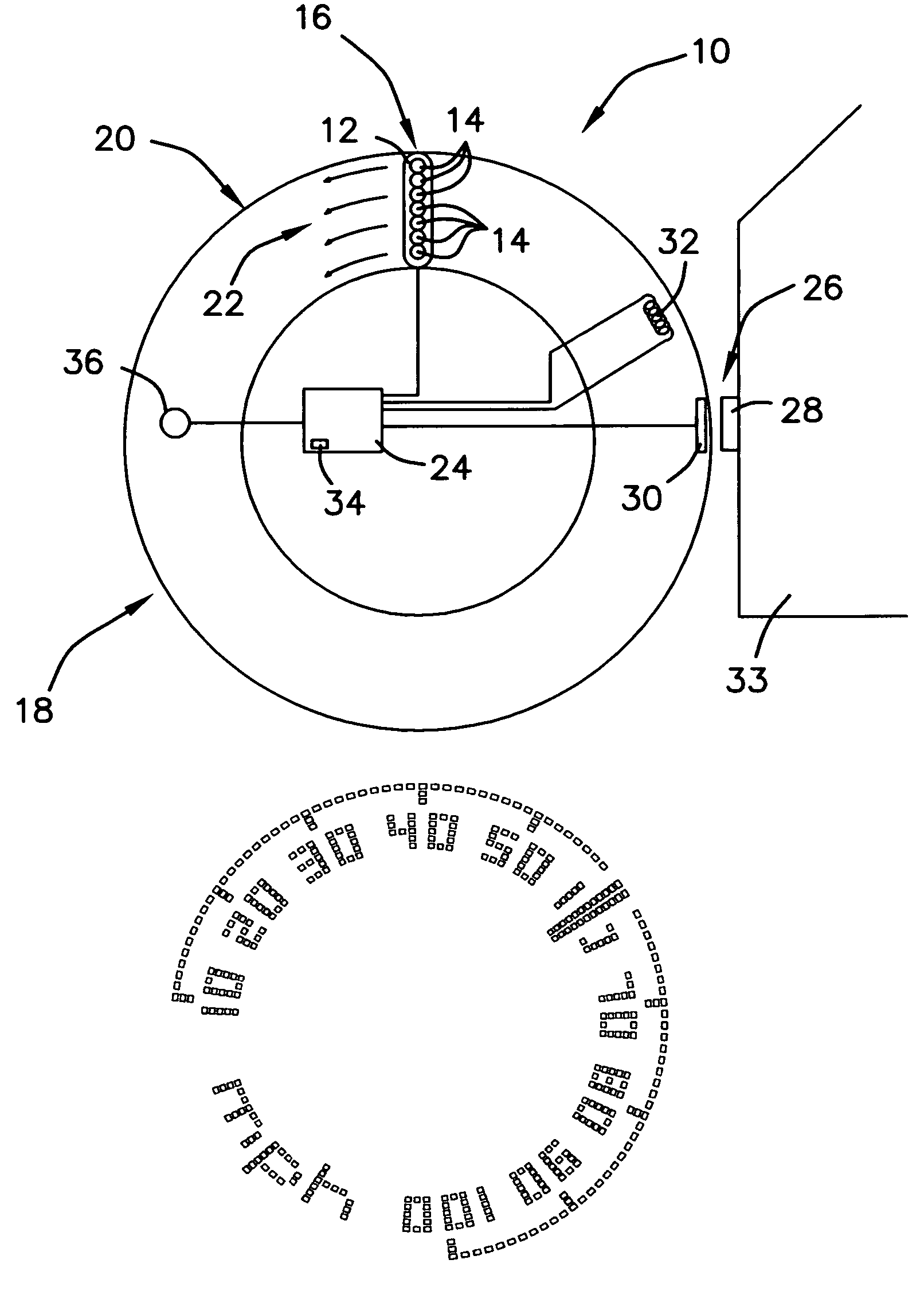
[0020]The present invention is a combination of hardware and software that flashes light emitting elements, such as light emitting diodes in such a way as to trace out an image or sequence of images when the apparatus is mounted on a rotating object.

[0021]For the purpose of this application for U.S. Letters Patent, the following terms are defined:

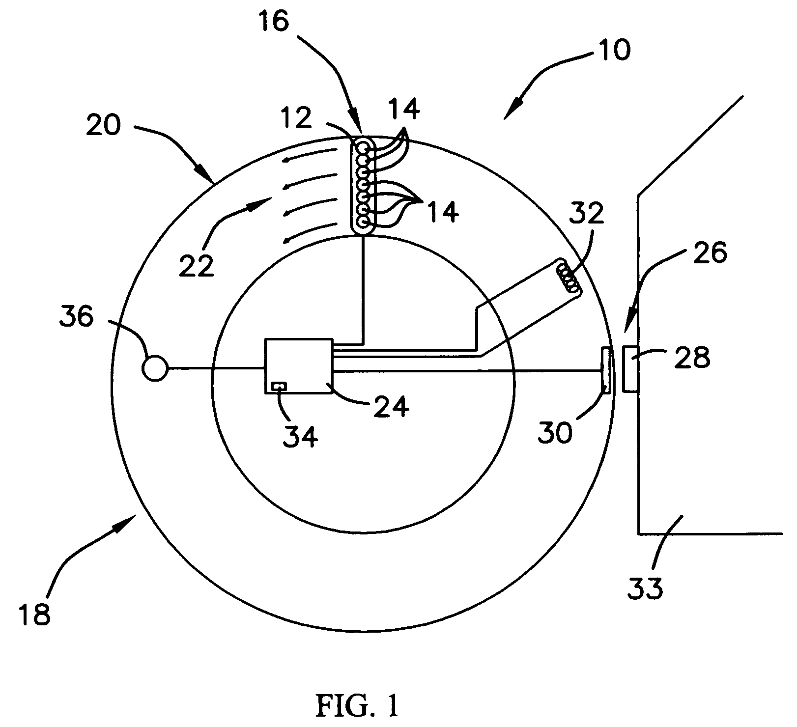
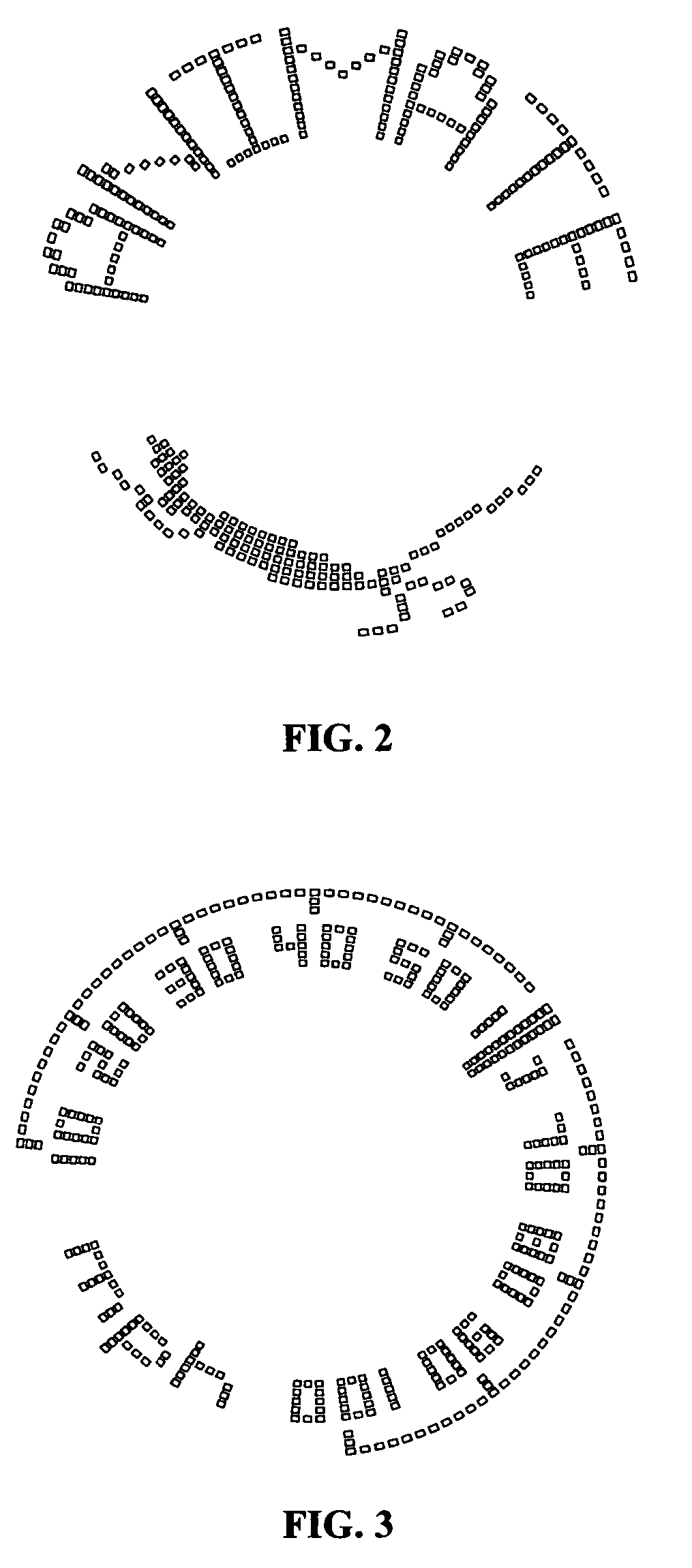
[0022]Rotational illumination is the affixation of a light or a plurality of lights to a rotational object to produce a sequence of pattern of light.

[0023]Light tail is defined as a plurality of light emitting elements, such a light emitting diodes affixed in a row and mounted along a radial direction on a rotational object.

[0024]Imaging is the electronic output of a predetermined image stored in memory.

[0025]Triggering is the steadying of an image scanned by Rotational Illumination via the positioning of a switching mechanism that is activated once or more per rotation. Thus the illumination device may begin to scan the image at the same a...


PUM


Abstract

A rotational light emitting display apparatus is provided. The rotational light emitting apparatus device allows static and animated images and instruments to be displayed on dynamic screen. The display is refreshed repeatedly to take advantage of the persistence of vision property of the human eye. The illuminating element of the apparatus includes a plurality of light emitting elements arranged in a line. Display refreshing is accomplished by mounting the apparatus on a rotating object, so that the line of light emitting elements lies along a radial direction. In this way, each of the light emitting elements traverse a circular path, while being flashed on and off to produce the desired display.

Description

BACKGROUND OF THE INVENTION[0001]1. Field of the Invention[0002]The present invention relates generally to aesthetic and decorative illumination, illuminated instrumentation, and illuminated display of animation. More particularly, relating to a rotational light emitting display apparatus capable of achieving aesthetic and decorative illumination, illuminated instrumentation, and illuminated display of animation.[0003]2. Description of the Prior Art[0004]It is desirable to display aesthetic and decorative illumination, advertisement, warning signs or signals or the like on rotating objects or on objects which move along an arcuate path, such as but not limited to hand held displays, vehicle wheels and fans and the prior art has attempted to fulfill this need.[0005]Examples of such prior art devices are described in the following U.S. patents: U.S. Pat. No. 6,265,984 to Molinaroli; U.S. Pat. No. 6,037,876 to Crouch; U.S. Pat. No. 5,800,039 to Lee; U.S. Pat. No. 6,072,386 to Yu; U.S. ...

Claims


Application Information

Patent Timeline
Patent Type & Authority Patents(United States)
IPC IPC(8): G09G3/00G09G3/32
CPCG09G3/005G09G3/32
Inventor MATLOCK, DANMATLOCK, PETER
Owner MATLOCK DAN
Why Eureka
Try Eureka