Method of detecting incomplete edge bead removal from a disk-like object

a technology of disklike objects and edge beads, which is applied in the field of detection of incomplete edge beads from disklike objects, can solve the problems of reducing the quality of subsequent layers, and the inability to detect complete edge beads with the apparatus, so as to facilitate quick and reliable detection

Active Publication Date: 2009-01-13
VISTEC SEMICON SYST
View PDF6 Cites 5 Cited by
  • Summary
  • Abstract
  • Description
  • Claims
  • Application Information

AI Technical Summary

Benefits of technology

[0009]It is therefore an object of the present invention to provide a method facilitating quick and reliable detection of incomplete edge bead removal with a plurality of wafers of a batch.

Problems solved by technology

Remaining photoresist residues on the periphery of the disk-like object can lead to reduced quality when subsequent layers are applied and when the dies are structured.
Detecting complete edge bead removal, however, is not possible with the apparatus shown here.

Method used


Image

  • Method of detecting incomplete edge bead removal from a disk-like object
  • Method of detecting incomplete edge bead removal from a disk-like object
  • Method of detecting incomplete edge bead removal from a disk-like object

Examples


Embodiment Construction

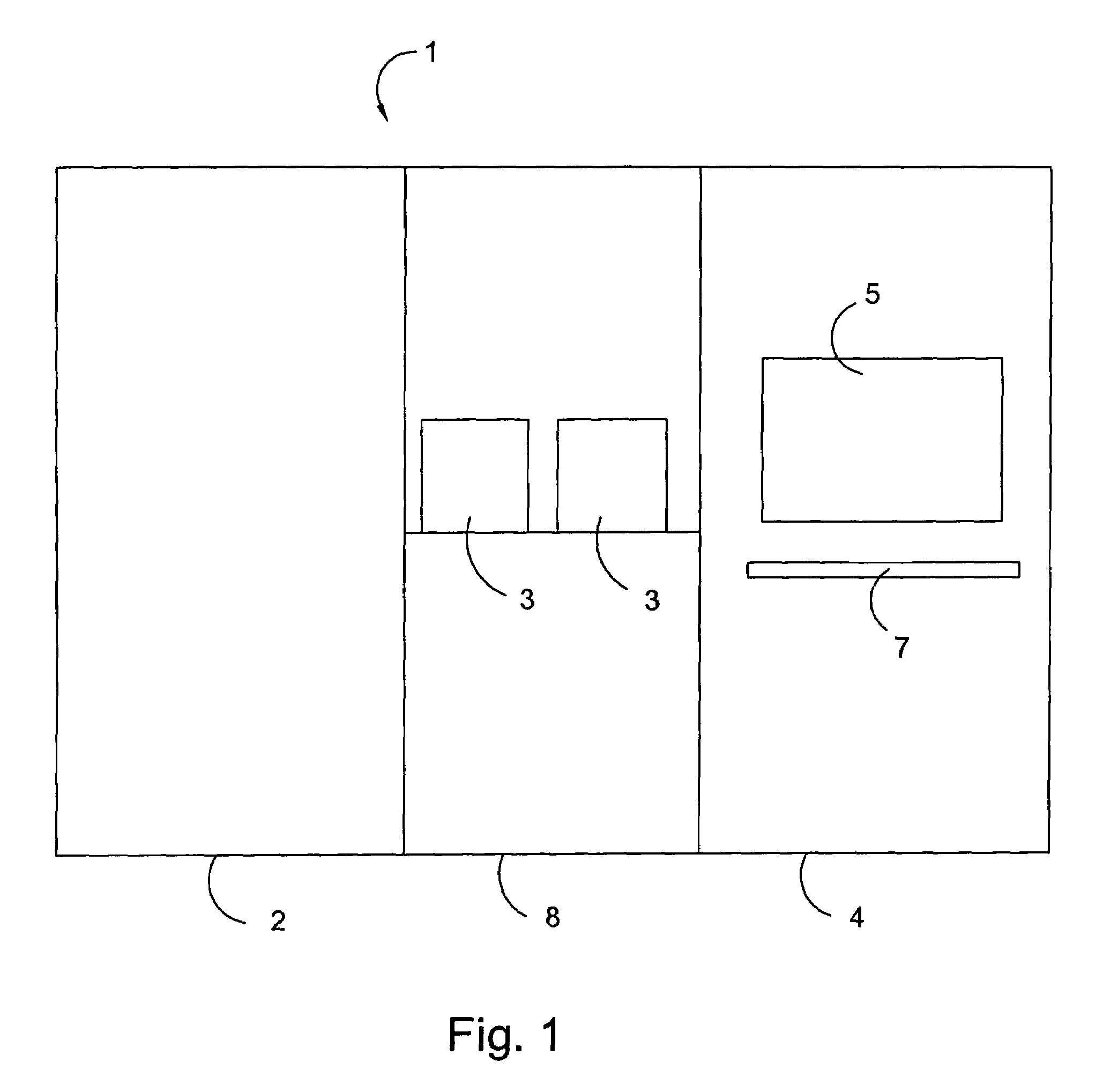
[0028]With reference to FIG. 1 an apparatus for inspecting a disk-like object or substrate is shown. Apparatus 1 for inspecting a disk-like substrate is comprised of a plurality of modules suitable for inspecting the disk-like object. In a first module 2, a macro inspection can be carried out. In a second module 4, subsequently, if necessary, a micro inspection of areas of interest on the disk-like object can be carried out. In the present embodiment a display 5 and an input unit 7 are provided on the second module allowing the user to enter respective specifications and parameters necessary for the inspection of the disk-like object. In the embodiment shown, the first module 2 and the second module 4 are connected via a third module 8. Containers 3 including the disk-like objects can be inserted on the third module 8 so that the disk-like objects can be introduced into apparatus 1 from the containers.

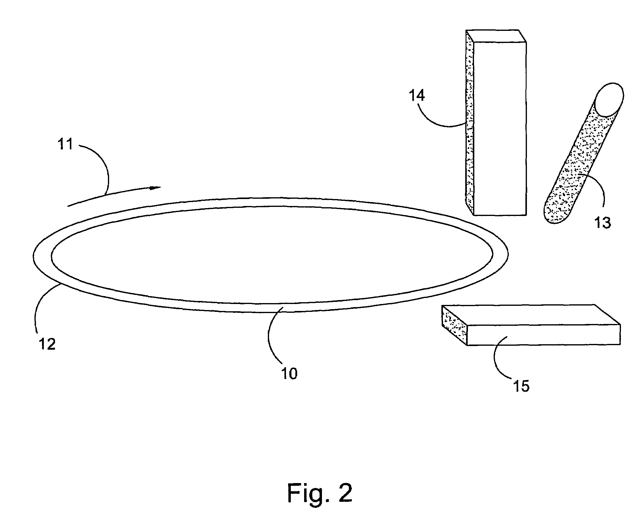
[0029]FIG. 2 is a perspective schematic view of the assembly for recording an imag...


PUM

PropertyMeasurementUnit
areaaaaaaaaaaa
areasaaaaaaaaaa
polarized lightaaaaaaaaaa

Abstract

A method of detecting incomplete edge bead removal from a disk-like object is disclosed. First a peripheral area of a disk-like reference object is imaged. Marks are then defined in the peripheral area of the reference object. Finally, images of peripheral areas of a plurality of disk-like objects of the same batch are recorded. The inspection of the disk-like objects is limited to the locations of the marks defined on the reference object.

Description

CROSS REFERENCE TO RELATED APPLICATIONS[0001]This patent application claims priority of German Patent Application No. 10 2005 014 594.9, filed on Mar. 31, 2005, which application is incorporated herein by reference.FIELD OF THE INVENTION[0002]The present invention relates to the detection of incomplete edge bead removal from a disk-like object.BACKGROUND OF THE INVENTION[0003]In semiconductor manufacture, during the manufacturing process, wafers (disk-like objects) are sequentially processed in a plurality of process steps, wherein a plurality of similar, repetitive structural elements, the so-called dies, are produced on a wafer.[0004]In order to produce the dies, a plurality of photoresist layers must be applied one after the other on the wafer. During processing of the wafer, these applied photoresist layers are removed in a peripheral area. Checking the sufficient and complete removal of these photoresist layers is of considerable importance for the subsequent process steps. Rem...

Claims


Application Information

Patent Timeline
Patent Type & Authority Patents(United States)
IPC IPC(8): G01N21/00G03B27/32
CPCG01N21/8803G01N21/9503G01N2021/8427G01N2021/8822G03F7/168
Inventor MICHELSSON, DETLEFBACKHAUSS, HENNINGWENIGER, GERT
Owner VISTEC SEMICON SYST
Why Eureka
Try Eureka