Method and device for optically inspecting faults

a technology of optical faults and optical inspection, applied in measurement devices, material analysis through optical means, instruments, etc., can solve the problems of limited object size, limited maximum simultaneously recordable surface, limited maximum dimension of light curtain, etc., and achieve economic effect and suitable properties

Active Publication Date: 2016-04-14
VIPROTRON
View PDF1 Cites 0 Cited by
  • Summary
  • Abstract
  • Description
  • Claims
  • Application Information

AI Technical Summary

Benefits of technology

[0030]According to one advantageous embodiment of the notion of the invention, the projection surface is an opaque pane of a translucent material. The shadowing of the object can be detected in this way on a side of the projection surface facing away from the object, so that the object moving, past the projection surface does not hinder the optical detection of the shadow image on the projection surface. At the same time, this makes it possible to dispose the light source, the device f...

Problems solved by technology

However, the size of the object is limited to the diameter of the telecentric lens or a front lens arranged therein.
After a diameter of several centimeters, telecentric lenses are hardly still economically advisable for the determination of dimensions of three-dimensional objects, on account of the high manufacturing costs.
The maximum si...

Method used


Image

  • Method and device for optically inspecting faults
  • Method and device for optically inspecting faults
  • Method and device for optically inspecting faults

Examples


Embodiment Construction

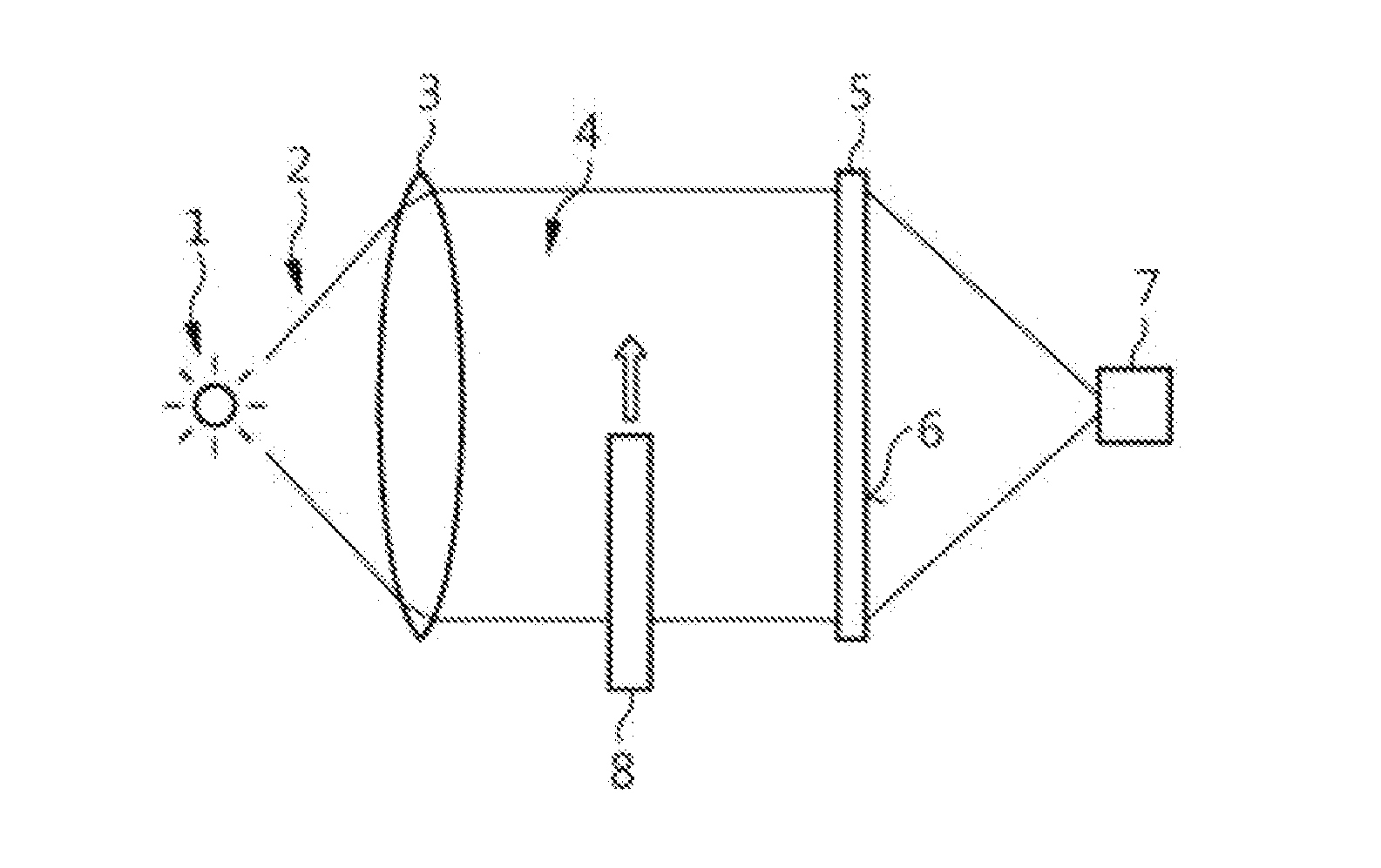
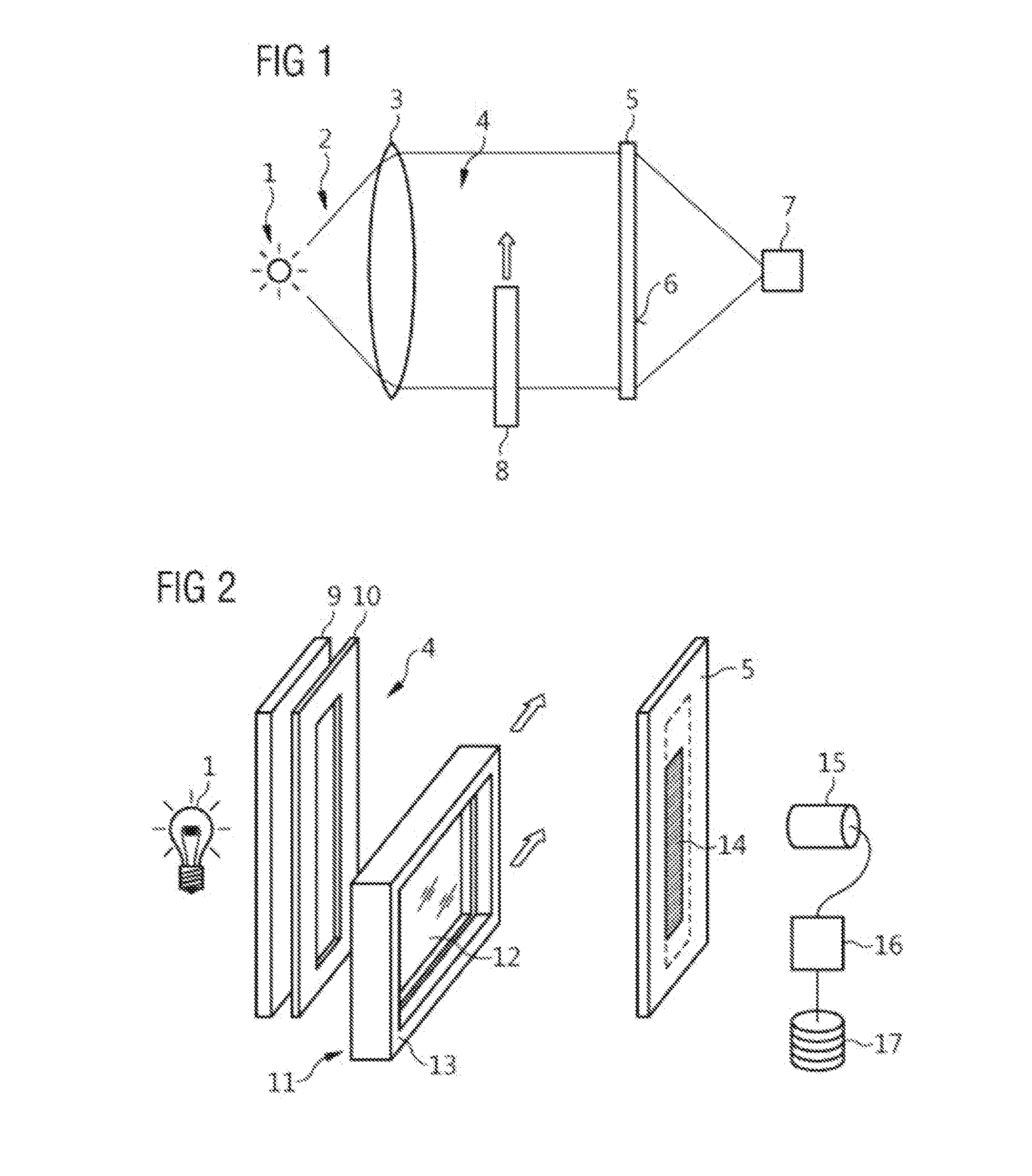
[0038]In a method for the optical inspection of a large-area three-dimensional object shown schematically in FIG. 1, a beam 2 of noncoherent light, is generated with a light source 1. Using a suitable optical component 3, an illumination surface 4 of parallel light beams is created, which is directed onto a projection surface 5. The projection surface 5 consists of a translucent pane with a matte surface 6. An optical detection device 7 is disposed on one side of the projection surface 5 located opposite the light source 1, with which an image of the projection surface 5 can be recorded.

[0039]The projection surface 5 is illuminated with parallel light beams from the illumination surface 4. An object 8 situated between the illumination surface 4 and the projection surface 5 casts a shadow on the projection surface 5. The shadow so cast can be detected and evaluated with the optical detection device 7.

[0040]When the object 8 moves through between the illumination surface 4 and the pro...


PUM


Abstract

In a method for optically checking a large-area three-dimensional object an illumination surface of parallel light beams is generated using a light source, a large-area three-dimensional object is partly or completely illuminated by the illumination surface, and a change of the parallel light beams of the illumination surface through the object is detected, wherein a projection surface is arranged on an object face opposite the light source, and the object shadow cast on the projection surface by the illumination surface is detected using an optical detection device. The strip-shaped light curtain is produced with a Fresnel lens. The shadow is detected using an optical lens system or a CCD camera. The dimensions of the object parallel to the projection surface are ascertained and compared with specified reference values. The projection surface is an opaque panel made of a translucent material or a surface-treated glass pane.

Description

BACKGROUND AND SUMMARY[0001]The invention concerns a method for optical fault inspection, or checking of an object, wherein an illumination surface is created from parallel light beams with a light source, wherein the object is at least partly illuminated by the illumination surface and wherein a change in the parallel light beams of the illumination surface by the object is detected.[0002]Such methods are used for example by a manufacturer for optical checking of glass panes. Another area of use of such test methods involves the inspection of framed glass panes and especially multiple glazed and framed window panes during and after their manufacture. Besides defects within the surface of the pane, these test methods serve to check the correct positioning of the glass panes relative to the frame elements. With such test methods one can determine whether a frame element was fixed in the intended position relative to the glass pane, or whether there is an unwanted skewing of the frame...

Claims


Application Information

Patent Timeline
IPC IPC(8): G01N21/958G01N21/88
CPCG01N21/958G01N2201/061G01N21/8806G01B11/2433
Inventor SANDNER, ANDREAS
Owner VIPROTRON
Why Eureka
Try Eureka