
Wet motor pump

A motor pump, wet technology, applied in the field of wet motor pump, can solve the problems of low strength, insufficient mechanical vibration, high noise, etc., and achieve the effect of good sealing

Inactive Publication Date: 2016-08-10
WILO SE
View PDF10 Cites 0 Cited by
  • Summary
  • Abstract
  • Description
  • Claims
  • Application Information

AI Technical Summary

Problems solved by technology

However, engineering thermoplastics have a lower strength compared to metals, which is largely dependent on boundary conditions such as temperature, operating pressure, medium
This often leads to increased technical effort in designing the product and thus to higher manufacturing costs and less favorable operating characteristics of the components and products
Due to the low density of plastics, mechanical vibrations are not transmitted sufficiently damped and can lead to higher noise generation of the product

Method used


Image

  • Wet motor pump
  • Wet motor pump

Examples


Embodiment Construction

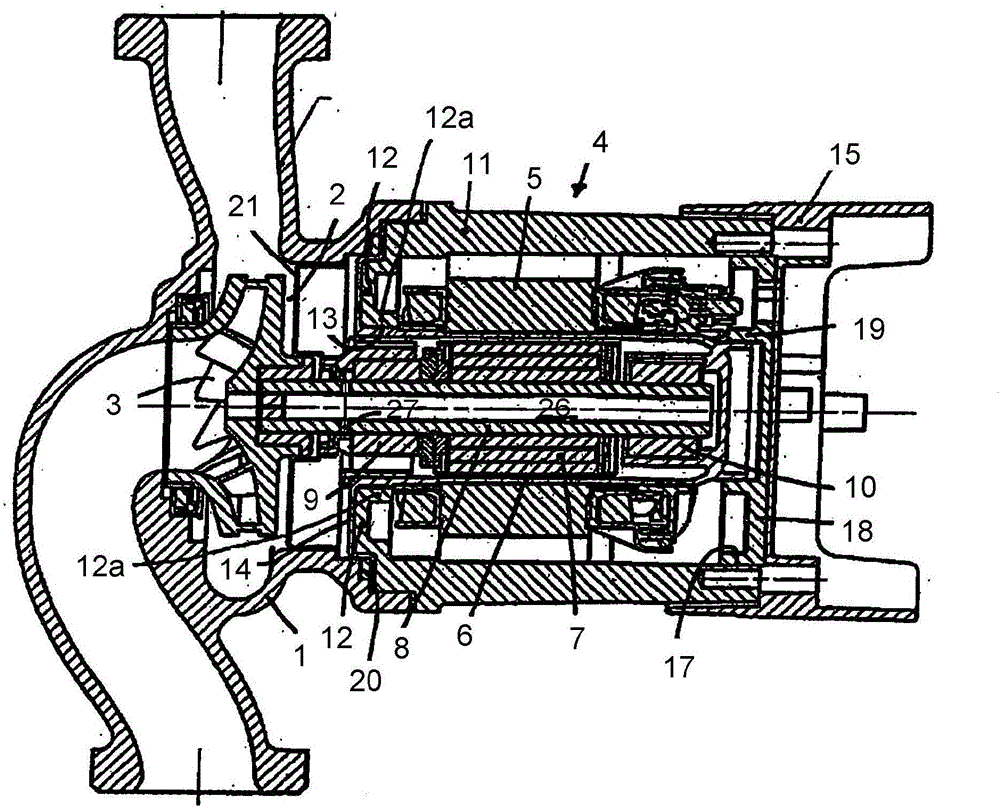
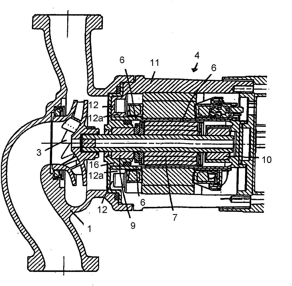
[0020] On the hydraulic side, the wet motor pump has a pump housing 1 which encloses a pump chamber 2 in which a pump impeller 3 runs. Coaxially fastened to the pump housing is a motor housing 4 which encloses a stator 5 in which a sealing pot 6 (or sealing tube) is attached which forms a rotor chamber in which the motor rotor 7 is located. running in the rotor chamber. The rotor 7 has a coaxial shaft 8 which is guided through two bearings 9 , 10 arranged inside the seal pot 6 and which carries the pump impeller 3 at one end.

[0021] On the outer wall 11 of the motor housing 4 , on the hydraulic system side, an inwardly directed annular motor housing flange 12 is integrally formed, on the inner end of which a ring-shaped extension is integrally formed. 12a, the free end of this extension is directed towards the stator 5 . The annular widening 12 a forms a coaxial central opening 13 which surrounds the sealing pot 6 on the outside in such a way that the annular widening rest...


PUM


Abstract

The invention relates to a wet motor pump comprising a stator (5) surrounded by a motor casing (4), and a rotor (7) which is separated from the stator by a can (6), runs in a rotor chamber formed by the can, and is connected to a pump impeller (3) via a shaft (8). At the end facing the pump impeller, the motor casing forms an inward-oriented motor casing flange (12), the inner end of which forms an annular extension (12a) that rests externally on the can either directly or via an intermediate layer.

Description

technical field [0001] The invention relates to a wet motor pump having a stator surrounded by a motor housing and a rotor separated from the stator by a seal pot, which runs in a rotor chamber formed by the seal pot and is connected to the pump impeller by a shaft connect. Background technique [0002] Wet pumps with EC motors are often equipped with sealed pots made of plastic. No eddy current losses occur in the sealed pot made of engineering plastics, which contributes to the efficient functioning of the motor. However, engineering thermoplastics have lower strengths than metals, which are largely dependent on boundary conditions such as temperature, operating pressure, medium. This often leads to increased technical effort in designing the product and thus to higher manufacturing costs and less favorable operating characteristics of the components and the product. Due to the low density of plastics, mechanical vibrations are not transmitted sufficiently damped and ca...

Claims


Application Information

Patent Timeline
Patent Type & Authority Applications(China)
IPC IPC(8): F04D13/06
CPCF04D13/0606
Inventor T·马特尔内
Owner WILO SE
Learn More