Robotic manipulator

a robot and manipulator technology, applied in the direction of mechanical control devices, instruments, process and machine control, etc., can solve the problems of limited range, limited vertical support of manipulable loads, and difficult assembly procedures, and the effect of requiring complex components

Inactive Publication Date: 2009-01-20
ROSS HIME DESIGNS
View PDF31 Cites 43 Cited by
  • Summary
  • Abstract
  • Description
  • Claims
  • Application Information

AI Technical Summary

Problems solved by technology

Although a number of such mechanical manipulators have been developed which to a greater or lesser degree achieve some of these desires therefor, most have been relatively complicated devices requiring complicated components and difficult assembly procedures or both.
Many, in addition, represent compromises in having relatively limited range, or singularities within the ranges, or other limitations in performance.
However, there is much less vertical support provided to loads on the manipulable support positioned at relatively extreme angles with respect to vertical in some radial positions.
In operation, the operation of any one actuator can not be controlled independently from the others because of the unavoidable coupling between the three pivoting links.
Yet, the reduced support provided to loads on a manipulable support in the manipulator, at least when positioned at relatively extreme angles with respect to vertical in some radial positions, remains a problem.
This problem arises because the pivoting links, the rotary joints, the actuators, and even the transducers used in measuring certain variables in the manipulator during use for the manipulator control system, are compliant, or flexible, under applied loads.
This yielding makes precision positioning of the manipulable support more difficult.
The problem is further compounded by nonlinear effects such as joint backlash.

Method used


Image

  • Robotic manipulator
  • Robotic manipulator
  • Robotic manipulator

Examples


Embodiment Construction

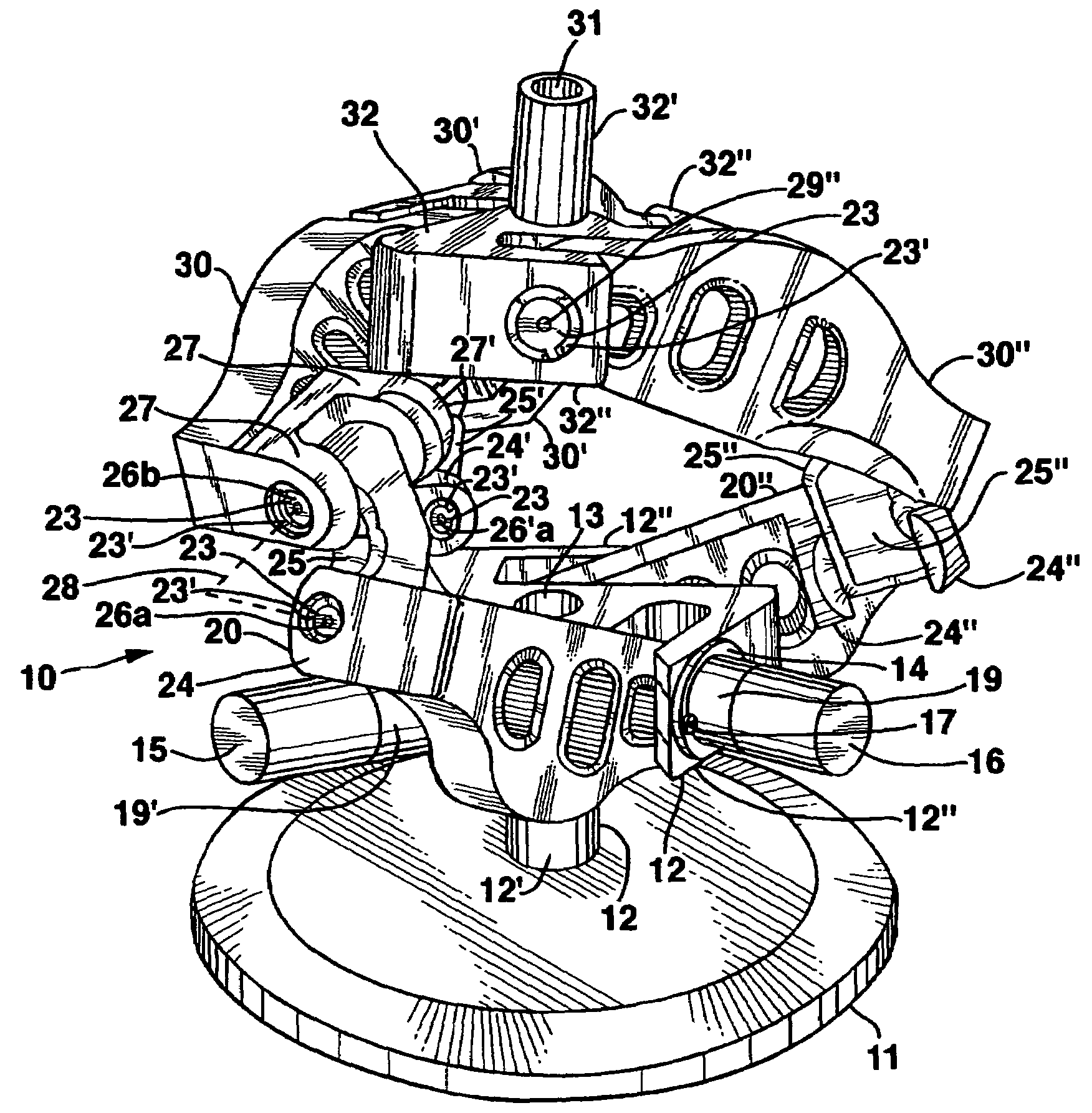
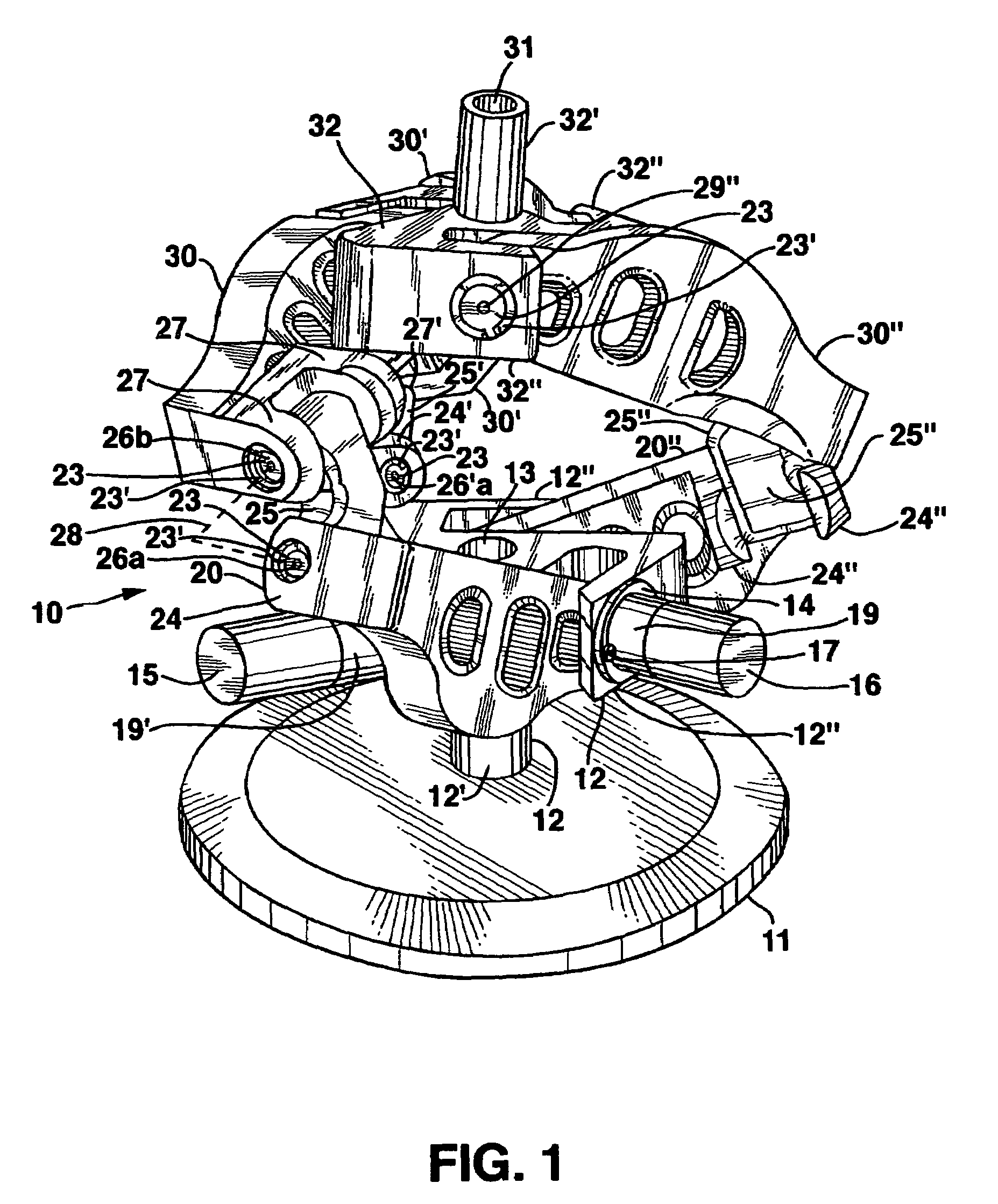
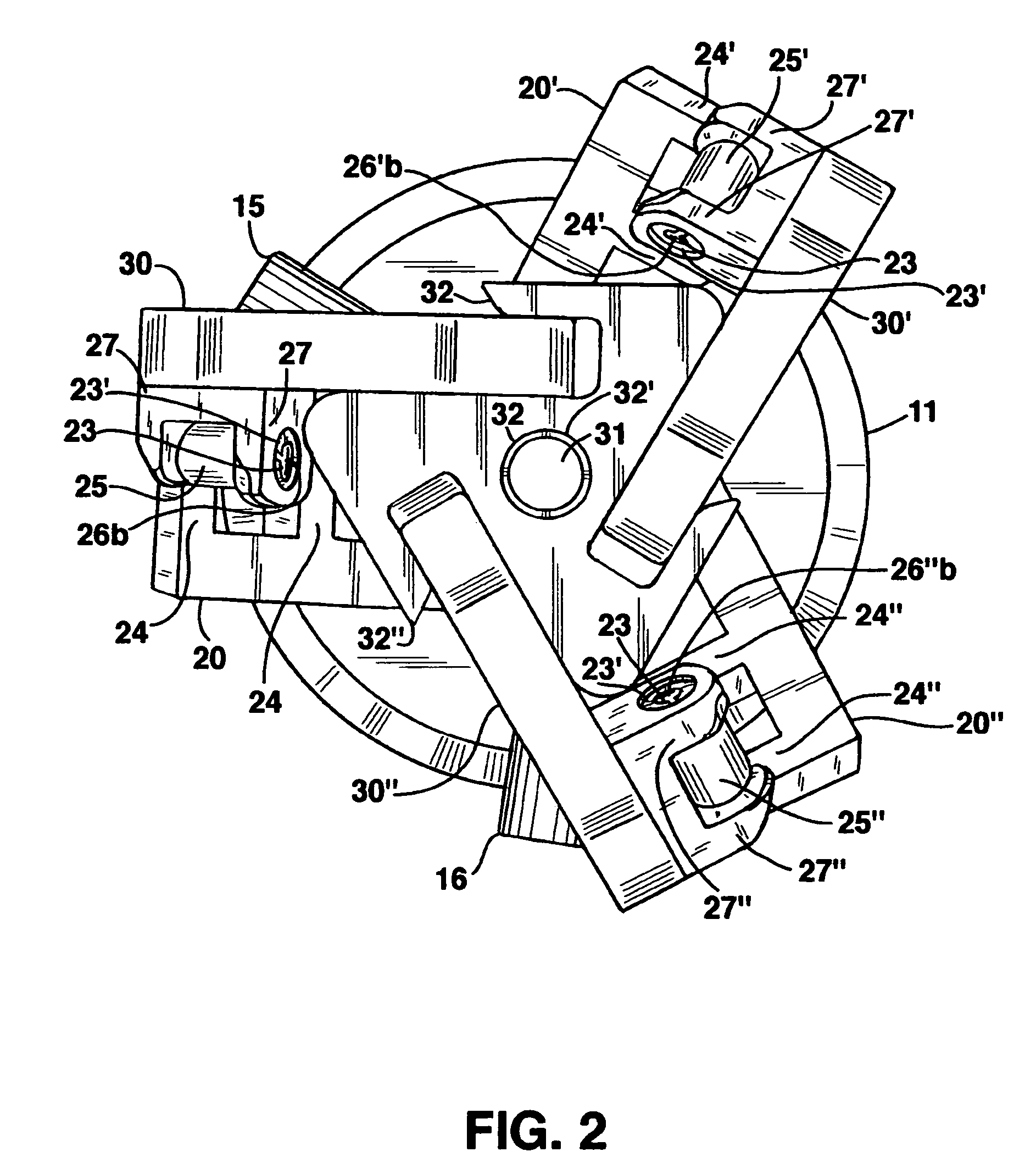
[0017]FIGS. 1 and 2 show a first embodiment of a mechanical manipulator, or controlled member motion system, 10, which can have a very large output operating range in various configurations over which it is free of singularities, and which is operated by various force imparting devices directly or through various kinds of drive trains. FIG. 1 shows an elevation view of manipulator 10 with FIG. 2 showing a top view thereof. Manipulator 10 is positioned on a mounting arrangement, 11, which can contain therein an electric motor arrangement, unseen in these figures, which can rotate mounting arrangement 11 in either the clockwise or counterclockwise direction as selected by the user to thereby carry the remainder of joint or manipulator 10 correspondingly with it in these directions.

[0018]Directly supported on mounting arrangement 11 is a base support, 12, shown as truncated cylindrical shell structure, 12′, affixed at one end thereof on mounting arrangement 11 and fixedly supporting on...


PUM


Abstract

A controlled relative motion system comprising a base support, a pivot holder and a plurality of pivoting links with the pivoting links rotatably coupled to both the base support and to members of the pivot holder to rotate about axes which extend in different directions for each of these rotatable couplings in a link, typically in accord with specific geometrical arrangements, and in different directions from similar axes in another of such links. The foregoing various rotatable couplings are provided by insertable bearings or bushings in the supports and links. The pivoting links have larger portions thereof outside of the interior of the manipulator parts of which can extend outside in different directions. Such systems can incorporate a variety of force imparting members to control movements of various ones of the pivoting links or pivot holder members.

Description

CROSS-REFERENCE TO RELATED APPLICATION[0001]This application claims the benefit of U.S. Patent Application No. 60 / 664,086, filed on Mar. 22, 2005.BACKGROUND OF THE INVENTION[0002]A strong desire for increased automation in the workplace, and a desire to increase the use of animated figures depicting animals, humans or other characters in entertainment and other situations, along with an increased ability to control such mechanical manipulators has led to substantial efforts in the development of robotics. As a result, significant advances have occurred in many aspects of robotics.[0003]Perhaps the most widely used controlled component in robotic systems is a mechanical manipulator, that portion of a robot often used in connection with an end effect or to change the position or orientation of selected objects engaged by that manipulator. In many instances, such mechanical manipulators are desired to have capabilities similar to those of the human wrist or shoulder, that is, exhibitin...

Claims


Application Information

Patent Timeline
Patent Type & Authority Patents(United States)
IPC IPC(8): B25J17/00B25J17/02B25J18/00
CPCB25J17/0266B25J9/0048Y10T74/20305Y10T74/20317Y10T74/20329Y10T74/20335
Inventor ROSHEIM, MARK E.
Owner ROSS HIME DESIGNS
Why Eureka
Try Eureka