
Inspection system and method

a technology of inspection system and method, applied in the field of inspection of areas, can solve problems such as blurry target images, and achieve the effect of enhancing long-range imaging

Inactive Publication Date: 2009-01-20
ENVIROSIGHT
View PDF31 Cites 20 Cited by
  • Summary
  • Abstract
  • Description
  • Claims
  • Application Information

AI Technical Summary

Benefits of technology

"The present invention provides a system and method for inspecting pipes by positioning the imaging head in the sweet spot, which is the area where the illumination source can focus its light beam. This allows for better imaging at longer ranges down the pipe compared to conventional inspection devices. The system includes a calibration capability to position the imaging head at a certain distance from the bottom of the pipe, an adjustability feature to ensure the imaging head is in the optimal position, and a stability feature to hold the imaging head in place. The method involves extending the imaging head into the manhole, placing the distal end on a rigid surface proximate the lateral pipe, and using a targeting fixture to aim the light beam for maximum illumination down the pipe. The invention also promotes the use of a lamp with narrow spot beams and a high intensity beam for maximum illumination and data gathering. Overall, the invention provides an inspection system that offers enhanced imaging and data gathering from a target in a pipe at a range longer than conventional devices."

Problems solved by technology

That is, if the vertical position of the imaging head is above or below the sweet spot initially, tilting the head will not rectify the situation, but rather cause the light beam to be angled relative to the pipe.
Imaging at relatively long range using high magnification requires the head to remain very still otherwise the target images will be blurry.
These are often opposing design objectives.

Method used


Image

  • Inspection system and method
  • Inspection system and method
  • Inspection system and method

Examples


Embodiment Construction

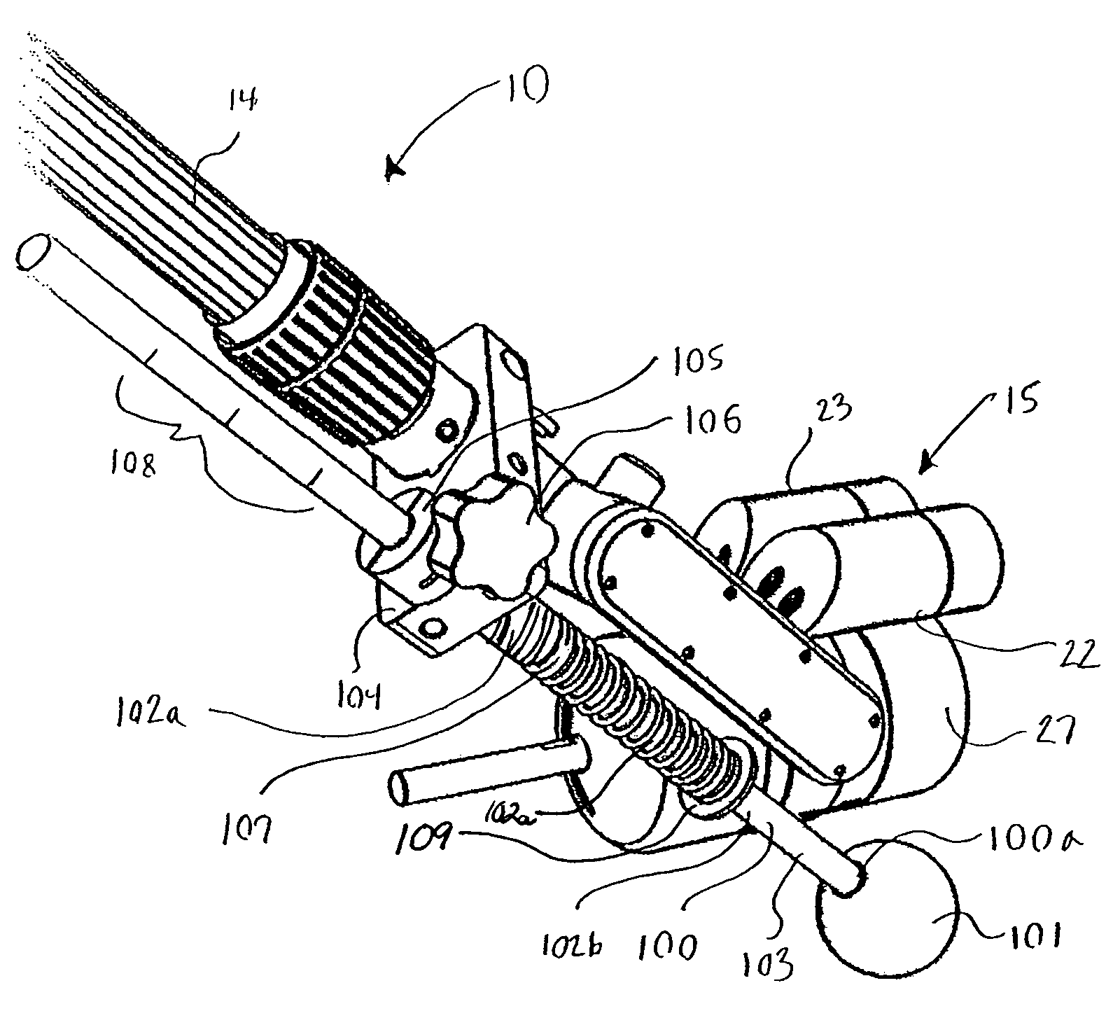
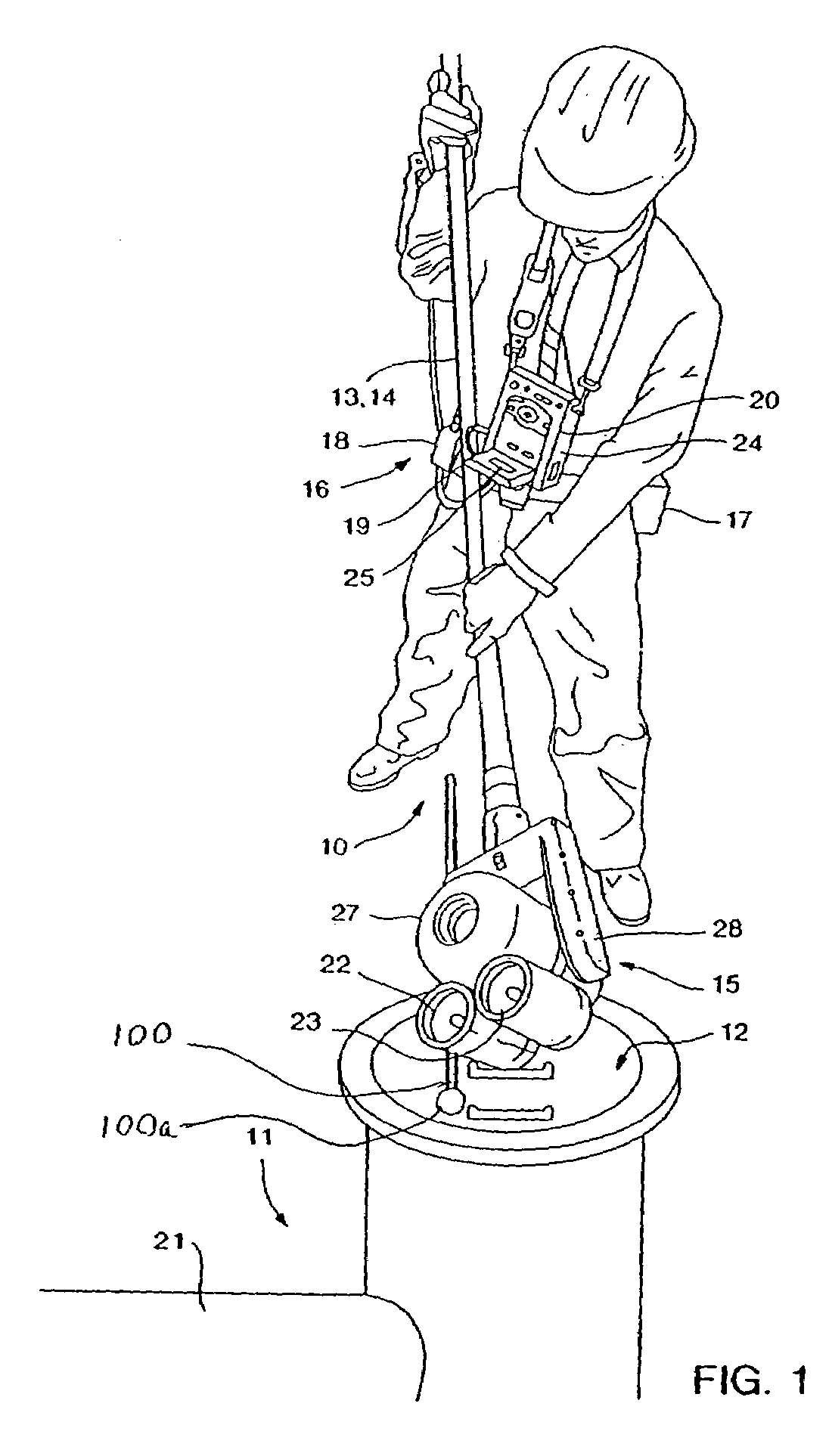
[0026]Referring to the drawings, FIG. 1 shows a user operating a preferred embodiment of the inspection system 10 to ascertain whether an invasive procedure is warranted. Using the system 10 comprises the steps of (a) extending an imaging head 15 into the manhole 12 using a positioning system 13, the imaging head 15 comprising an imaging device (within enclosure 27) and at least one lamp 23 capable of producing a light beam (not shown), the positioning system comprising an elongated member 14 and a targeting fixture 100 operatively connected thereto, the imaging head 15 being attached to one end of the elongated member 14, the targeting fixture 100 having a distal end 100a biased outwardly from the imaging head 15; (b) placing the distal end 100a on a rigid surface proximate to the lateral pipe 21; (c) pushing down on the elongated member 14 such that the distal end 100a resiliently moves toward the imaging head 15, thereby allowing the light beam to be centered approximately in the...


PUM

PropertyMeasurementUnit
focal lengthaaaaaaaaaa
diameteraaaaaaaaaa

Abstract

A method of inspecting a lateral pipe extending from a manhole, the method comprising: (a) extending an imaging head into the manhole using a positioning system, the imaging head comprising an imaging device and at least one lamp capable of producing a light beam, the positioning system comprising an elongated member and a targeting fixture operatively connected thereto, the imaging head being attached to one end of the elongated member, the targeting fixture having a distal end biased outwardly from the imaging head; (b) placing the distal end on a rigid surface proximate to the lateral pipe; (c) pushing down on the elongated member such that the distal end resiliently moves toward the imaging head, thereby allowing the light beam to be centered approximately in the lateral pipe; and (d) imaging a target located within the lateral pipe.

Description

REFERENCE TO RELATED APPLICATIONS[0001]This application claims priority to U.S. Provisional Patent Application No. 60 / 726,918 filed Oct. 14, 2005, the contents of which is hereby incorporated by reference.FIELD OF INVENTION[0002]The present invention relates generally to the inspection of areas that are hard-to-reach, inaccessible or uninhabitable for humans. More specifically, the invention relates to the inspection of manholes and lateral pipes radiating therefrom prior to invasive procedures such as cleaning and comprehensive exploratory inspections.BACKGROUND OF THE INVENTION[0003]It is often necessary to inspect and maintain areas under conditions that render them inaccessible or otherwise uninhabitable for humans for an extended period. These conditions include, for example, small confined spaces and harsh environments such as insufficient air / oxygen, presence of toxins, radioactivity, contamination, excessive dust, dirt and filth, and high noise levels. These conditions can b...

Claims


Application Information

Patent Timeline
Patent Type & Authority Patents(United States)
IPC IPC(8): G01N21/00G03B17/00G01M99/00
CPCG01N21/94G01N21/954G01N2021/9544G01N2201/021
Inventor LINDNER, RICHARD
Owner ENVIROSIGHT
Learn More