Low IF receiver systems and methods

a receiver and low-intermediate frequency technology, applied in the field of radio receivers, can solve the problems of degrading the performance of portable transceivers, fundamental limitations of edge systems in particular and digital communications in general, and traditional non-practical use of dcr systems

Active Publication Date: 2009-01-20
INTEL CORP
View PDF6 Cites 5 Cited by
  • Summary
  • Abstract
  • Description
  • Claims
  • Application Information

AI Technical Summary

Problems solved by technology

DCR systems have traditionally not been employed in practical applications until recently.
This is largely due to problems with direct current (DC) offset.
In EDGE modulation, for example, DC offset that is added to the signal can degrade performance of portable transceivers.
More particularly, DC offset can impair received signals, especially at low-signal levels, often resulting in fundamental limitations in EDGE systems in particular and digital communications in general.
Solutions to reduce added DC offset often introduce non-linearity at low-signal levels, add increased componentry (and thus consume more space and power), and may add to the complexity (and cost) of a system.
Although this averaging / subtraction process may work for GSM, EDGE presents different challenges.
In a time-division multiple access (TDMA) system such as GSM / EDGE, the phase of an added DC offset may change somewhat randomly from burst to burst, making long term averaging of DC offsets difficult.
A further problem that can arise with DCR systems is in the manufacturing process.
Semiconductor fabrication processes with good 1 / f noise characteristics are relatively expensive.
This approach adds a significant cost to a radio as it normally requires expensive filtering components as well as a second set of mixer hardware.
Some problems common to DCR systems may still exist in low IF receiver systems.
In low IF receivers operating in an interference limited environment such as GSM, receiver impairments (e.g., gain imbalance, phase imbalance, etc.) may cause some portion of the energy of adjacent channel interferers (in particular, the energy of the opposite sideband of the 2nd adjacent channel since fold over due to RF impairments is symmetric about 0 Hertz (Hz)) to fall directly in the bandwidth of the received signal and thereby degrade receiver performance.
A further problem is that typical low IF systems for GSM use a low intermediate frequency of 100 kHz, which may result in a 100 kHz interferer tone added to the desired signal at the radio output.
With EDGE modulation, however, the use of a notch filter to remove the 100 kHz tone may degrade system performance.

Method used


Image

  • Low IF receiver systems and methods
  • Low IF receiver systems and methods
  • Low IF receiver systems and methods

Examples


Embodiment Construction

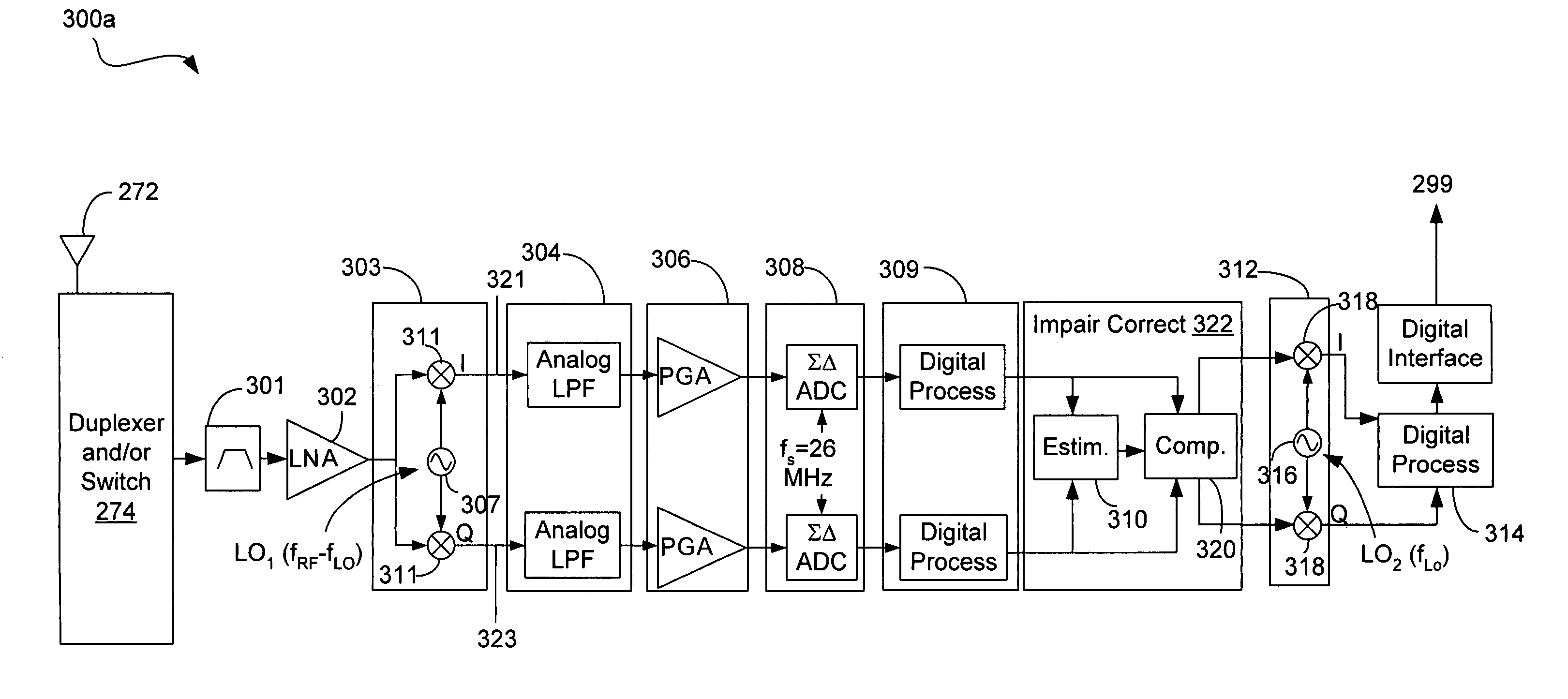
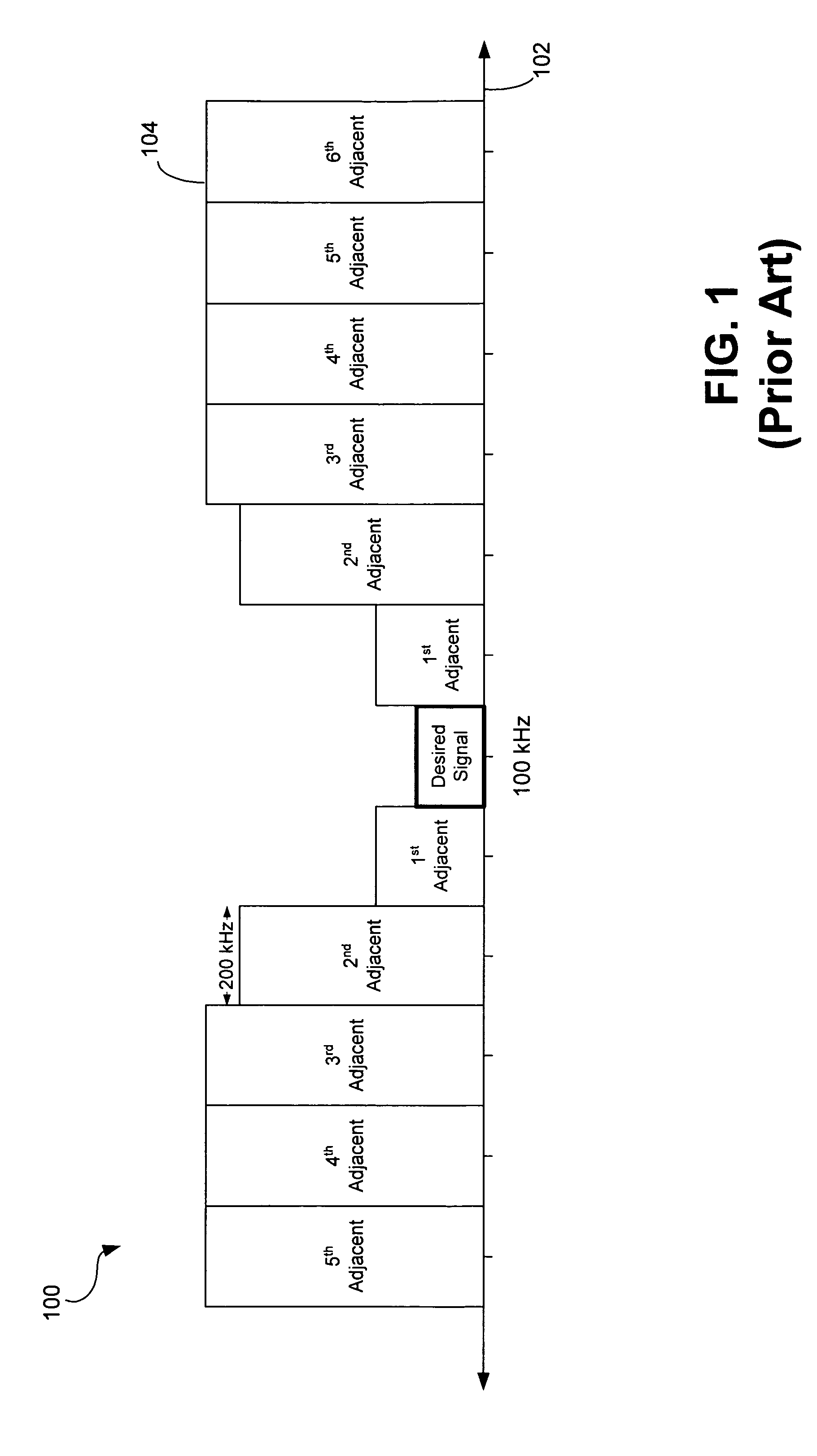
[0021]Embodiments of a low intermediate frequency (IF) receiver system and related methods are disclosed. In one embodiment, a low IF receiver system mitigates interfering energy from adjacent channels by reducing the level of radio frequency (RF) impairments due to imbalances in gain and / or phase. The in-band interference energy that is caused by RF impairments is proportional to the product of the RF impairments and the energy associated with one or more adjacent channel interferers. As the energy of an adjacent channel interferer increases, the impairments need to decrease to maintain the same level of in-band interference. A low IF receiver system is disclosed that digitally estimates the impairments and corrects or compensates for these impairments in the digital domain.

[0022]Although a low IF receiver system that estimates and compensates for the RF impairments may reduce the effective level of the RF impairments, some portion of the adjacent channel interferer may still fall ...


PUM


Abstract

Embodiments of a low intermediate frequency system and method are disclosed. In one embodiment, among others, a method for operating a receiver is disclosed that comprises receiving a radio frequency signal, downconverting the radio frequency signal to a downconverted signal comprising an in-phase component and quadrature component, and estimating a gain and phase imbalance between the in-phase component and the quadrature component.

Description

BACKGROUND OF THE INVENTION[0001]1. Field of the Invention[0002]This invention relates generally to radio receivers. More particularly, the invention relates to low intermediate frequency receivers.[0003]2. Related Art[0004]Simple textbook models of radio receivers typically use homodyne detection. Homodyne detection involves directly demodulating a radio frequency (RF) signal to baseband in a single operation. A receiver that implements homodyne detection is commonly referred to as a direct conversion receiver (DCR). Current state of the art radio receivers for Global System for Mobile Communication / Enhanced Data Rates for GSM Evolution (GSM / EDGE) use DCR systems at least in the EDGE mode. DCR systems have traditionally not been employed in practical applications until recently. This is largely due to problems with direct current (DC) offset. DC offset generally refers to the DC voltage at the output of a system that is unrelated to the signal at the input to the system. An interfe...

Claims


Application Information

Patent Timeline
Patent Type & Authority Patents(United States)
IPC IPC(8): H04L27/00
CPCH04B1/30H04L27/3863H04B1/1036H04B1/109H04B1/26H04L27/34
Inventor BEAMISH, NORMAN J.DOMINO, WILLIAM J.DAMGAARD, MORTEN
Owner INTEL CORP
Why Eureka
Try Eureka