Vacuum valve

a valve and vacuum technology, applied in the field of vacuum valves, can solve the problems of deficient valve tightness, large closing force, relative large force to be applied to tightly close the valve, etc., and achieve the effect of uniform distribution of for

Active Publication Date: 2009-01-27
VAT HLDG AG
View PDF36 Cites 10 Cited by
  • Summary
  • Abstract
  • Description
  • Claims
  • Application Information

AI Technical Summary

Benefits of technology

[0010]It has been shown that the force required for tightly closing the vacuum valve can be reduced by the construction of the valve disk according to the invention compared to a conventional rigid, plane valve disk known, e.g., from U.S. Pat. No. 4,458,905 B or DE 44 46 947 C2. In an embodiment of the invention, the required closing force can be reduced by half.
[0012]A more uniform distribution of force can also be achieved by the inventive construction of the valve disk with an elasticity in case of deviations in roundness of the sealing surface of the valve disk or of the sealing surface of the valve body or of the sealing surfaces of the sealing ring.

Problems solved by technology

However, a disadvantage of this vacuum valve consists in that the force to be applied for tightly closing the valve (closing force) is relative large.
While this reduces the required closing force, this closing force is still relatively large.
A disadvantage of this valve consists in that a deficient tightness of the valve can result even with very close tolerances of the geometry of the disk and sealing surface of the valve body, for example, roundness defects.
Also, snap effects can occur when the valve is opened, particularly when the valve has been heated.
For this reason, this vacuum valve has not had practical success.
Further, relatively slight geometric inaccuracies in this vacuum valve lead to deficient tightness of the valve.

Method used


Image

  • Vacuum valve
  • Vacuum valve
  • Vacuum valve

Examples


Embodiment Construction

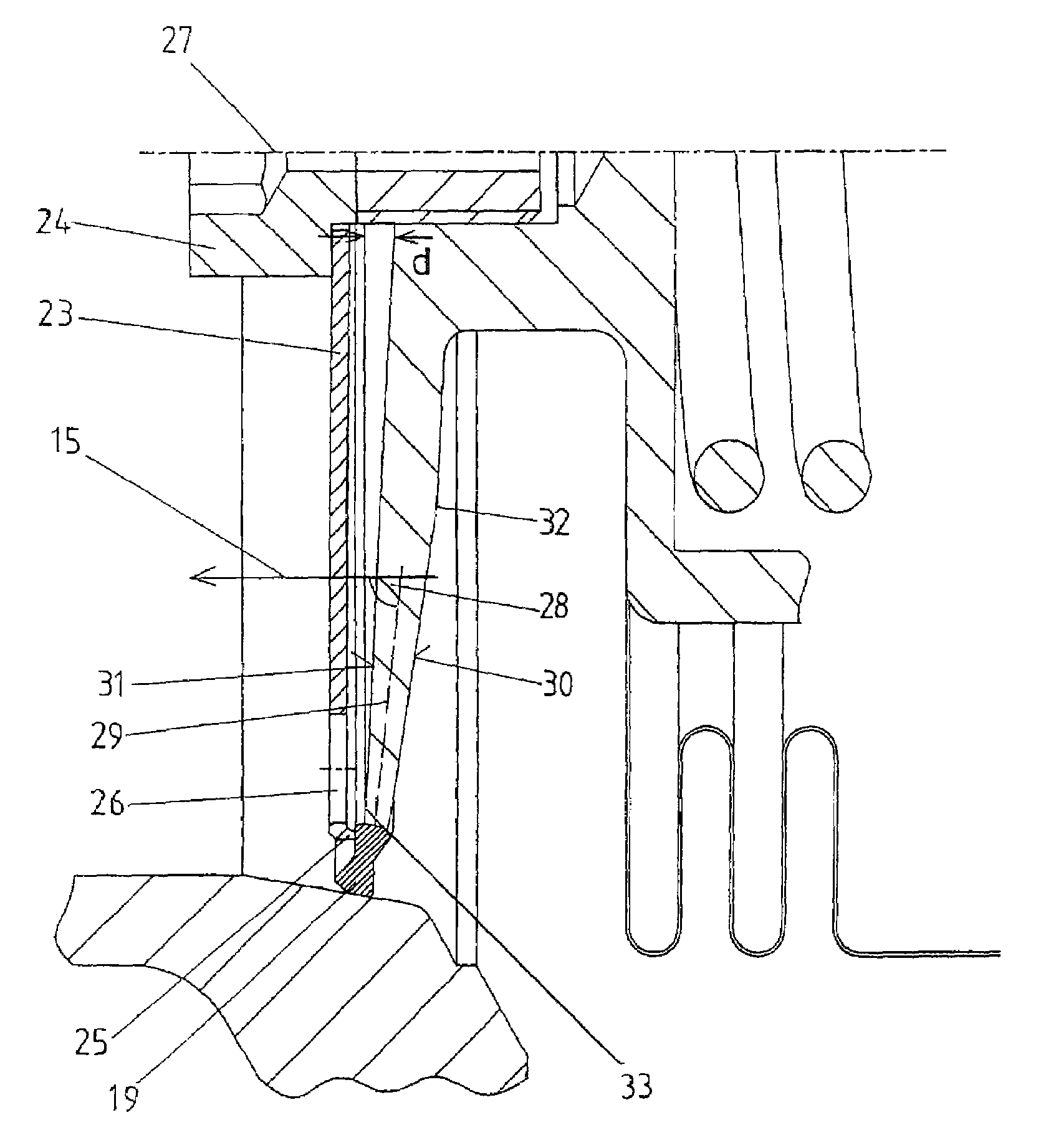
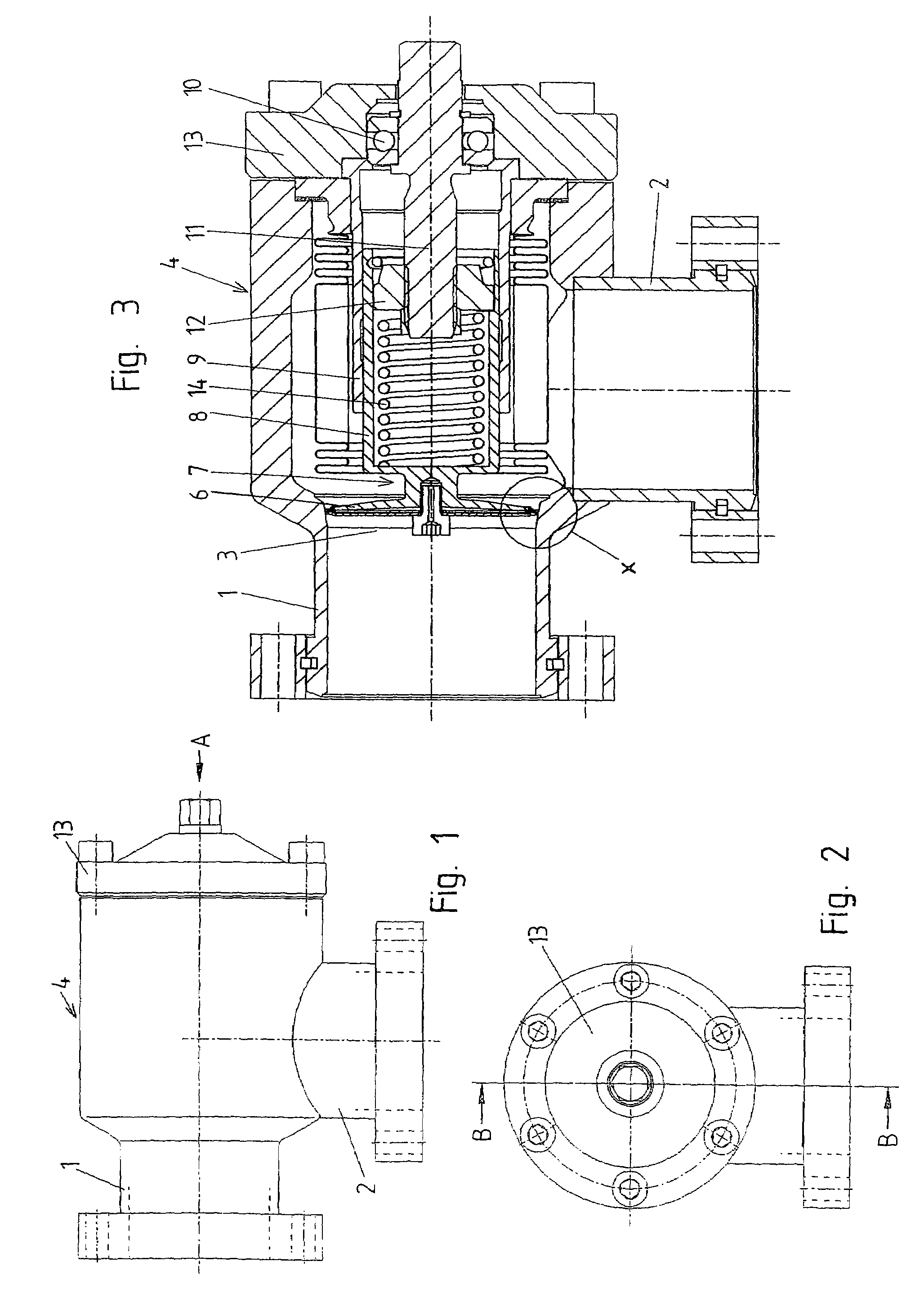
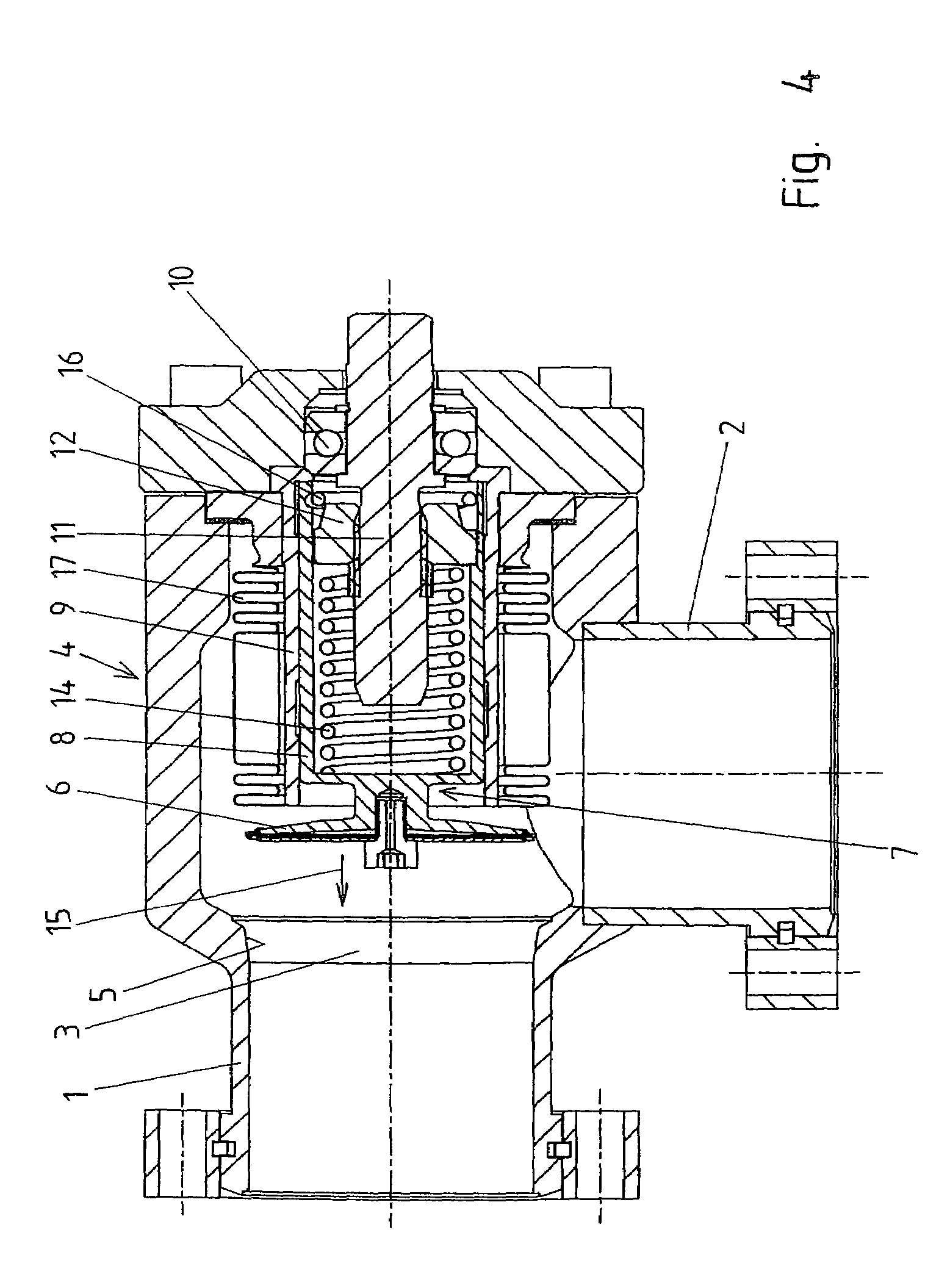
[0033]In the embodiment form of the invention shown in FIGS. 1 to 6, the vacuum valve is constructed as a corner valve in which the connection pieces 1, 2 extend at an angle, preferably at a right angle, to one another. The valve opening 3 is surrounded by a sealing surface 5 which is arranged at the valve body 4. The valve body 4, in its entirety, forms the housing of the vacuum valve.

[0034]A valve disk 6 can be displaced between an open position (FIG. 4) and a closed position (FIGS. 3, 5 and 6) in the sealed state of the vacuum valve. For this purpose, the valve disk 6 is arranged in the region of its center axis at a supporting part 7. In this embodiment example, this supporting part 7 is connected to a widened cup-shaped portion 8. The cup-shaped portion 8 is guided in a guide sleeve 9 so as to be axially displaceable. A spindle 11 which is rotatably mounted by means of a ball bearing 10 and on which a spindle nut 12 is arranged is used for axial displacement. The spindle nut 12...


PUM

PropertyMeasurementUnit
angleaaaaaaaaaa
angleaaaaaaaaaa
angleaaaaaaaaaa

Abstract

A vacuum valve comprises a conical sealing surface arranged at a valve body, a valve disk at which a conical sealing surface is arranged, and a sealing ring having a first sealing surface and a second sealing surface. The valve disk, the valve body and the sealing ring are made of metal at least in the areas of the sealing surfaces. The valve disk is constructed so as to be curved or angled considered in axial section through the center and encloses an angle of less than 90° with the closing direction in the unloaded state at least in a radial outer portion adjoining the sealing surface. The valve disk has an elasticity such that a displacement of the radial outer edge of the valve disk relative to a point in the center of the valve disk of at least 0.1% of the diameter of the valve disk in direction of the center axis of the valve disk is bought about in the closed position of the valve disk relative to the open position of the valve disk by an elastic deformation of the valve disk.

Description

CROSS-REFERENCE TO RELATED APPLICATION[0001]This application claims priority of German Application No. 10 2005 004 987.7, filed Feb. 2, 2005, the complete disclosure of which is hereby incorporated by reference.BACKGROUND OF THE INVENTION[0002]a) Field of the Invention[0003]The invention is directed to a vacuum valve with a conical sealing surface which is arranged at a valve body and which surrounds a valve opening, a valve disk which is rotationally symmetrical with respect to its center axis and at which a conical sealing surface is arranged and which is displaceable between an open position in the open state of the vacuum valve and a closed position in the sealed state of the vacuum valve, the movement of the valve disk when closing the vacuum valve taking place, at least in a final part of the closing movement before reaching the closed position, in a closing direction extending parallel to the center axis of the valve disk, and with a sealing ring having a first sealing surfac...

Claims


Application Information

Patent Timeline
Patent Type & Authority Patents(United States)
IPC IPC(8): F16K31/383F16J3/00
CPCF16K41/10F16K51/02
Inventor MAYER, THOMASDUELLI, BERNHARD
Owner VAT HLDG AG
Why Eureka
Try Eureka