Electrical connector assembly

a technology of electrical connectors and connector assemblies, applied in the direction of coupling device connections, electrical equipment, coupling protection earth/shielding arrangements, etc., can solve the problems of friction between the contact pins and wear to the connector assembly components, damage to the connector assembly, and intermittent or inadequate electrical connections of the interface, so as to minimize electrical interference or greater clearance

Active Publication Date: 2009-01-27
CREGANNA UNLTD
View PDF16 Cites 61 Cited by
  • Summary
  • Abstract
  • Description
  • Claims
  • Application Information

AI Technical Summary

Benefits of technology

[0006]An advantage of the present invention is a rectangular configured electrical connector assembly, which provides greater clearance between contacts, thereby minimizing electrical interference or cross-talk between the contacts.
[0007]Yet another advantage of the present invention is the communication capability of the contacts, which may provide communication for data, power, fluids, or any combination thereof.
[0008]Still another advantage of the present invention is a latching mechanism, which may provide a tactile and/or audible notificatio

Problems solved by technology

Connector assemblies that include rotary interfaces or other uniquely shaped or configured mechanical or electrical interfaces may experience intermittent or inadequate electrical connections if the contacts used within the connector experience feedback or interference.
The repeated cycles cause friction between the contact pins and wear to the connector assembly components.
In addition to withstanding the wear sustained by a connector assembly during normal use, a connector assembly must also be resi

Method used


Image

  • Electrical connector assembly
  • Electrical connector assembly
  • Electrical connector assembly

Examples


Embodiment Construction

[0019]Exemplary embodiments of the present invention are now described with reference to the figures. Reference numerals are used throughout the detailed description to refer to the various elements and structures. In other instances, well-known structures and devices are shown in block diagram form for purposes of simplifying the description. Although the following detailed description contains many specifics for the purposes of illustration, anyone of ordinary skill in the art will appreciate that many variations and alterations to the following details are within the scope of the invention. Accordingly, the following embodiments of the invention are set forth without any loss of generality to, and without imposing limitations upon, the claimed invention.

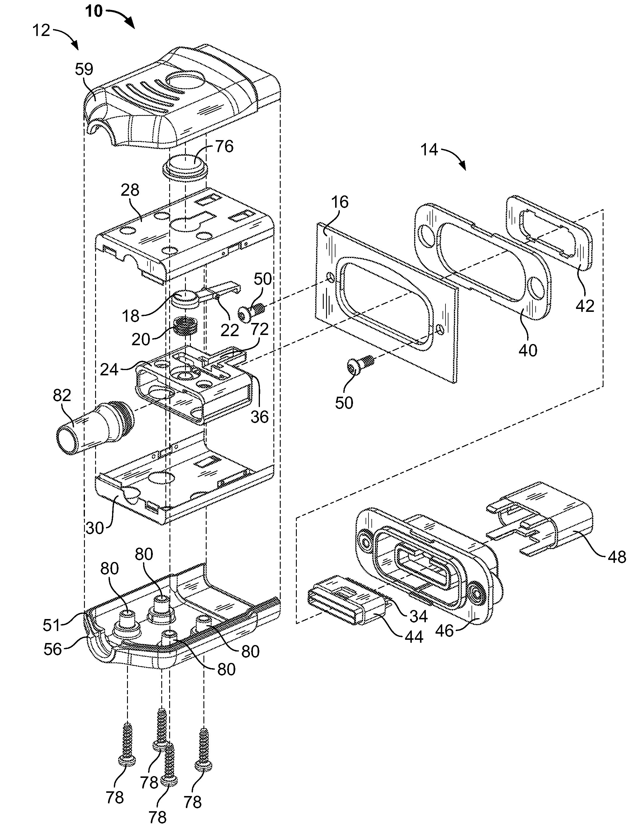
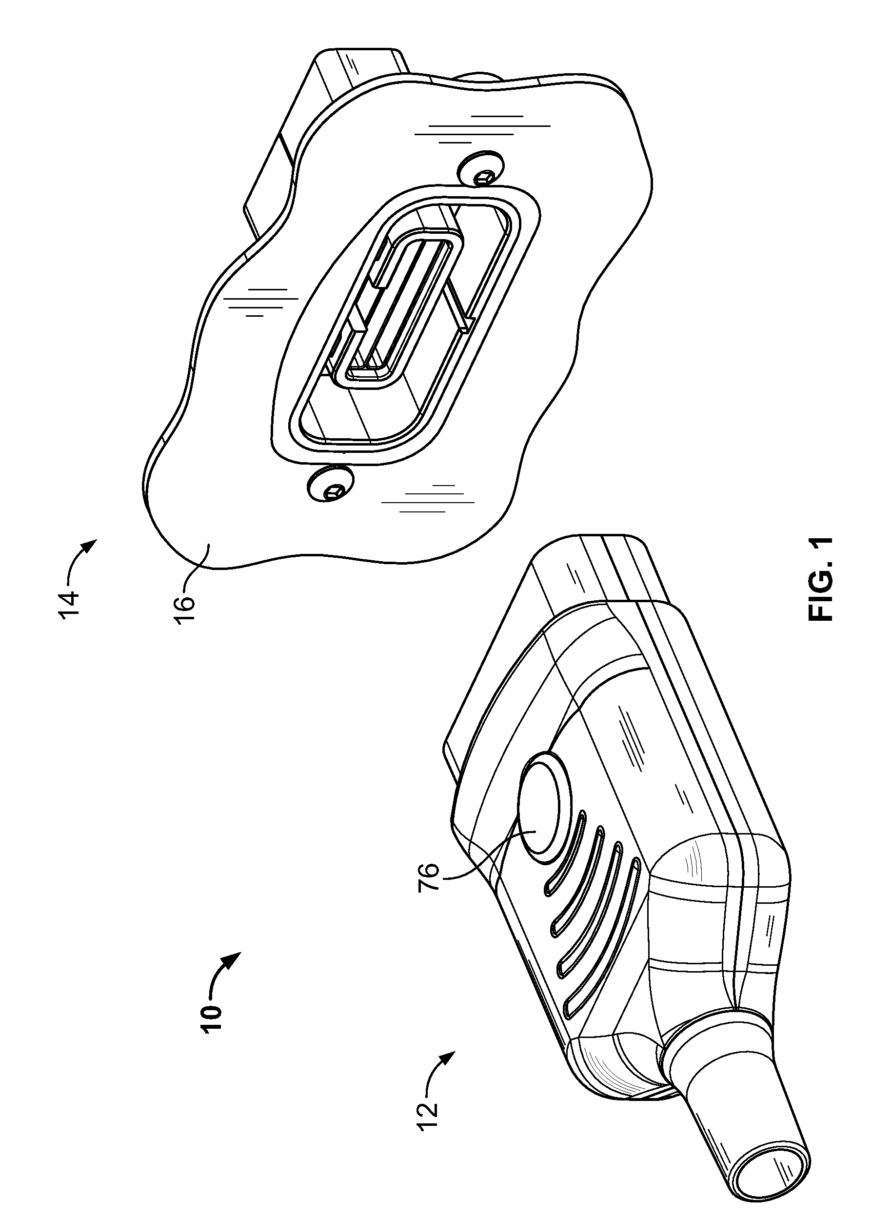
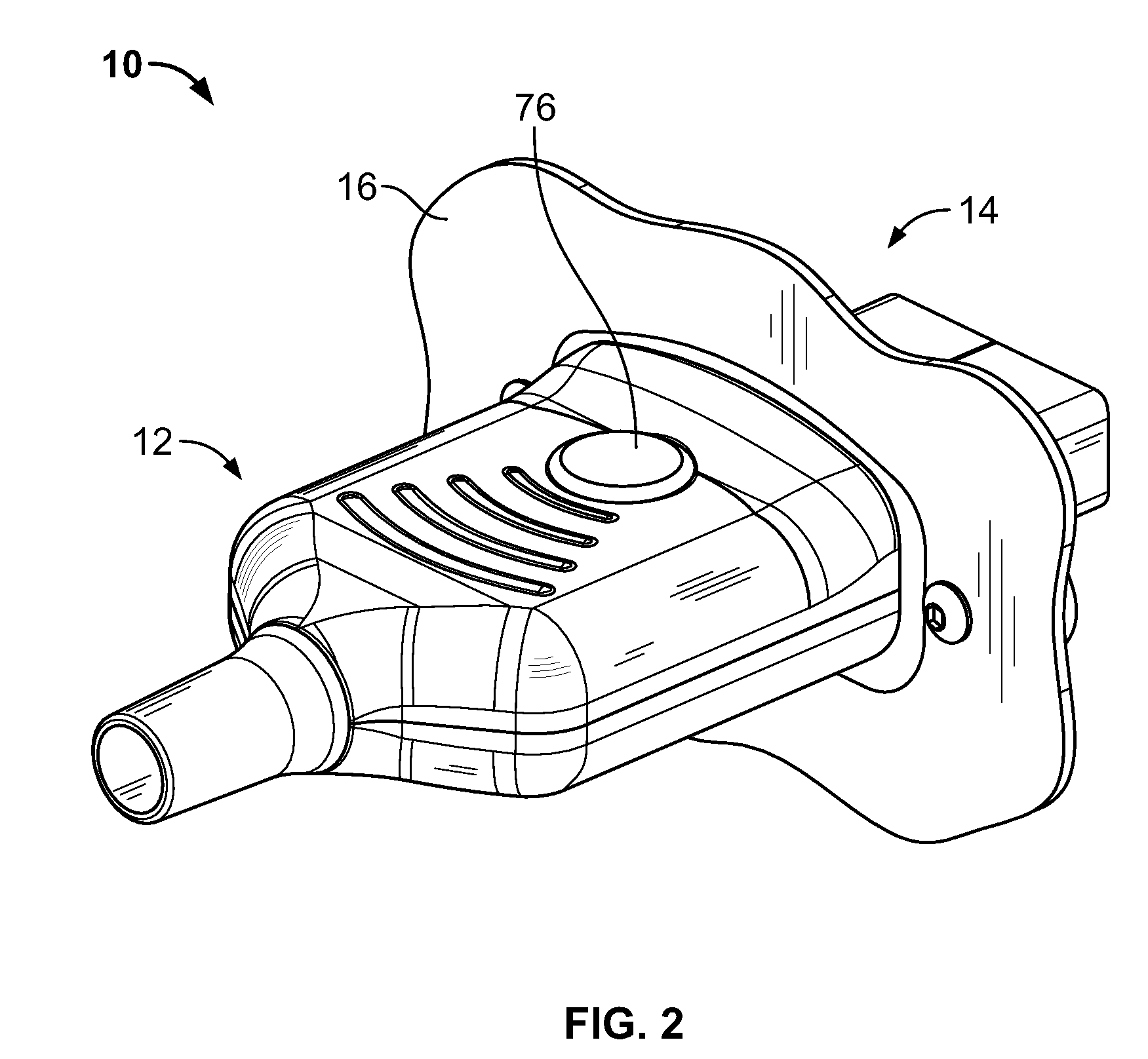
[0020]FIGS. 1-3 show an embodiment of an electrical connector assembly 10. Electrical connector assembly 10 may be used with surgical, medical or any other suitable applications. Electrical connector assembly 10 has a male portion...


PUM


Abstract

An electrical connector assembly is disclosed. A rectangular plug and rectangular receptacle engage to provide a sealed and durable connector. The electrical connector assembly provides electric, fluid, data and other suitable information suitable for surgical, medical or other device applications. A latch is used to secure the plug with the receptacle and prevent the plug from being easily removed from the receptacle. The connector is substantially sealed to prevent fluid, dust particles and/or other matter from entering the components and damaging the connector assembly.

Description

FIELD OF THE INVENTION[0001]The present invention is directed to an electrical connector assembly. More specifically, the present invention is directed to a reusable, rectangular electrical connector assembly.BACKGROUND OF THE INVENTION[0002]Surgical and medical devices utilize connector assemblies for electronic and power communication. It is particularly important in surgical and medical devices to establish and maintain reliable electrical connections in connector assemblies, even after many uses. Connector assemblies that include rotary interfaces or other uniquely shaped or configured mechanical or electrical interfaces may experience intermittent or inadequate electrical connections if the contacts used within the connector experience feedback or interference. Connector assemblies are repeatedly engaged and disengaged in normal use of surgical or medical devices. The repeated cycles cause friction between the contact pins and wear to the connector assembly components. In addit...

Claims


Application Information

Patent Timeline
IPC IPC(8): H01R13/627
CPCH01R13/6275H01R13/648H01R13/512H01R13/5224
Inventor KNOLL, JOHN K.FAROLE, DOMINIC A.BECK, TIMOTHY M.
Owner CREGANNA UNLTD
Why Eureka
Try Eureka