Turbine engine temperature control system with heating element for a gas turbine engine

Inactive Publication Date: 2014-09-18
SIEMENS AG
View PDF6 Cites 33 Cited by
  • Summary
  • Abstract
  • Description
  • Claims
  • Application Information

AI Technical Summary

Benefits of technology

[0003]A turbine engine temperature control system configured to limit thermal gradients from being created within an outer casing surrounding a turbine airfoil assembly during shutdown of a gas turbine engine and for preheating an engine during a cold startup is disclosed. By reducing thermal gradients caused by hot air buoyancy within the mid-region cavities in the outer casing, arched and sway-back bending of the outer casing may be prevented, thereby reducing the likelihood of blade tip rub, and potential blade damage, during a warm restart of the gas

Problems solved by technology

Because of the mass of these large gas turbine engines, the engines take a long time to cool down after shutdown.
Many of the components cool at different rates and as a result, interferences develop between various components.
Thus, if it is desired to startup the gas turbine before is has comp

Method used


Image

  • Turbine engine temperature control system with heating element for a gas turbine engine
  • Turbine engine temperature control system with heating element for a gas turbine engine
  • Turbine engine temperature control system with heating element for a gas turbine engine

Examples


Example

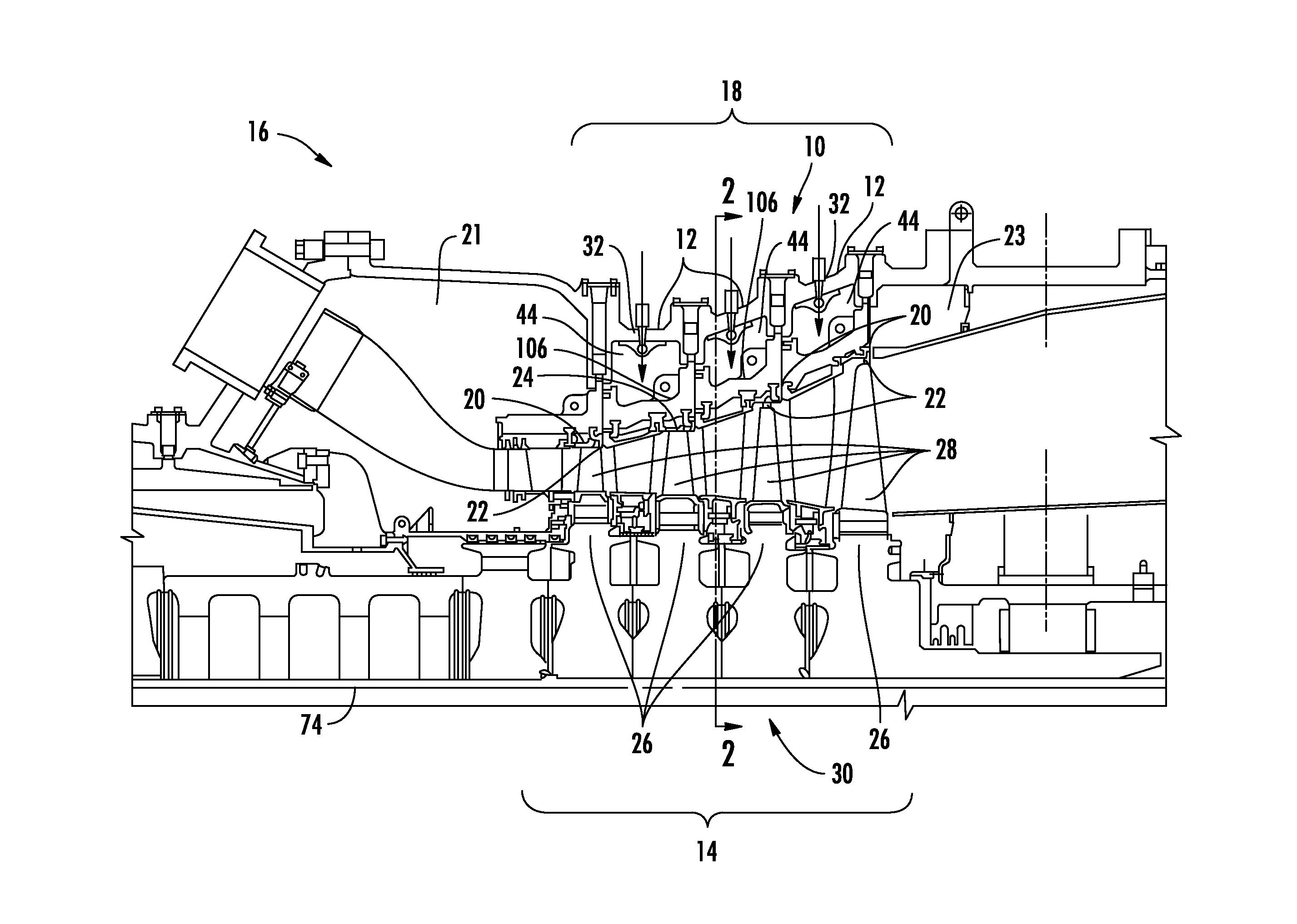
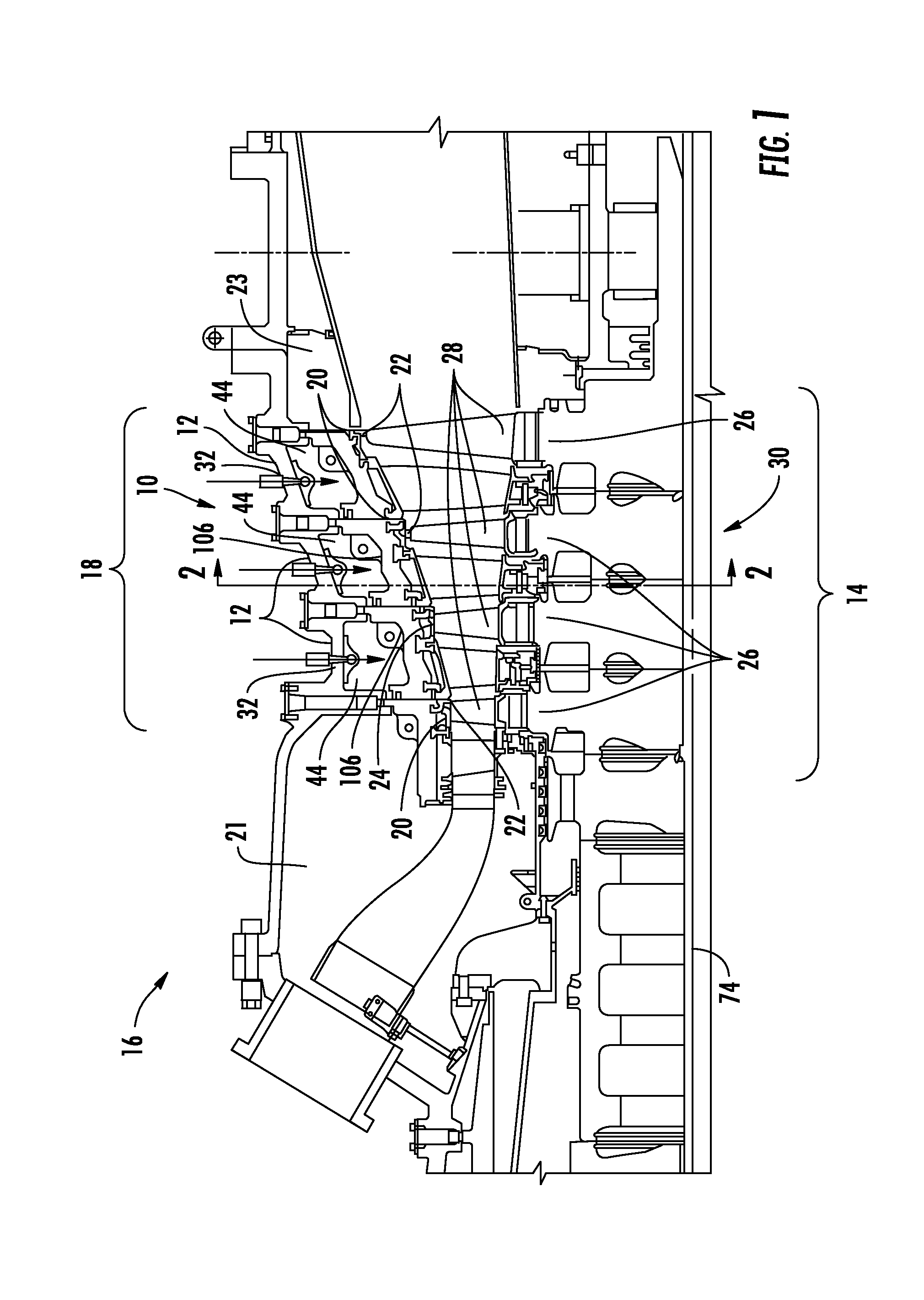
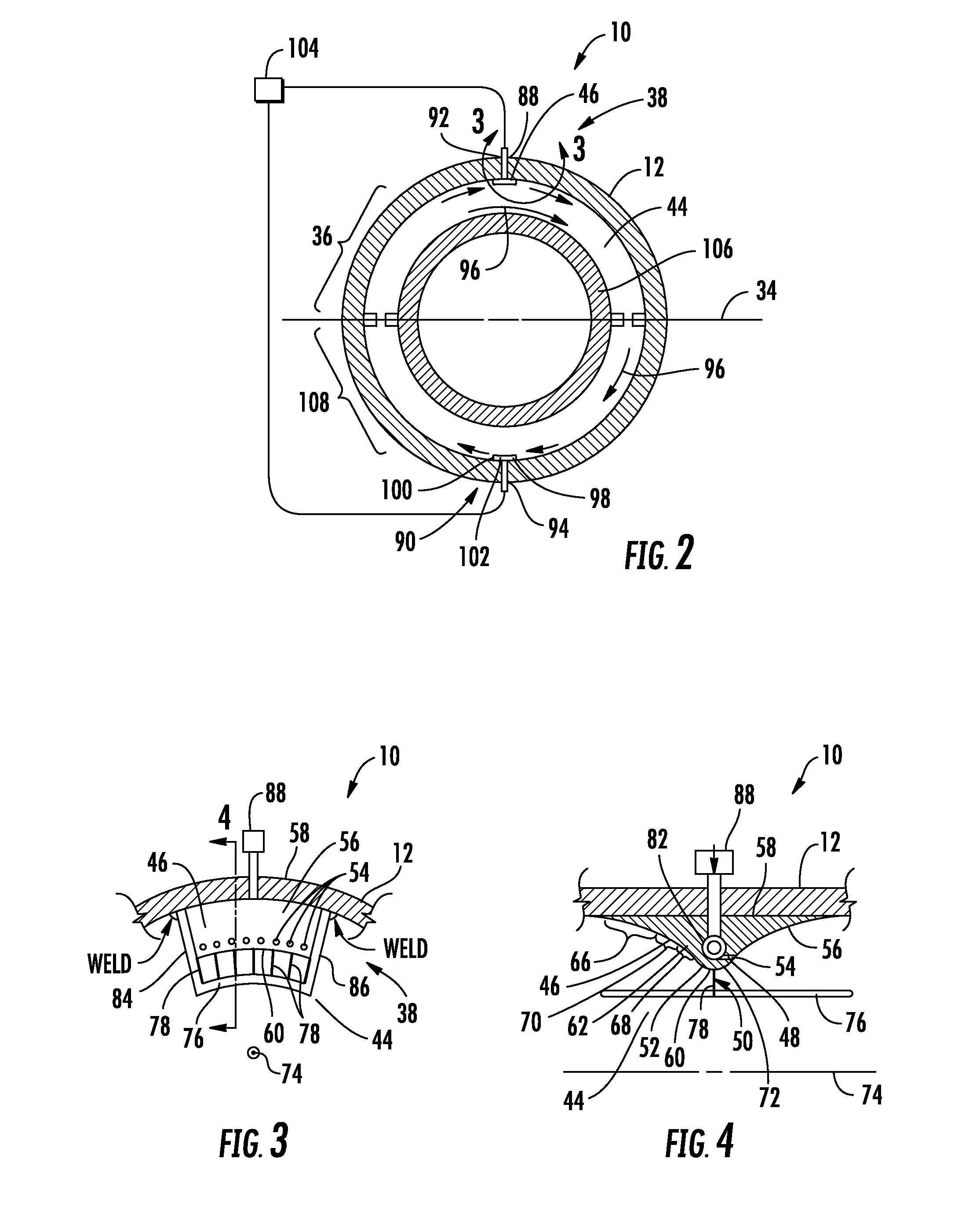
[0030]As shown in FIGS. 1-4, a turbine engine temperature control system 10 configured to limit thermal gradients from being created within an outer casing 12 surrounding a turbine airfoil assembly 14 during shutdown of a gas turbine engine 16 and for preheating an engine 16 during a cold startup is disclosed. The turbine engine temperature control system 10 may also be configured to limit thermal gradients in midframe cavities 21 and in exhaust cavities 23. By reducing thermal gradients caused by hot air buoyancy within the mid-region cavities 18 in the outer casing 12, arched and sway-back bending of the outer casing 12 may be prevented, thereby reducing the likelihood of blade tip rub, and potential blade damage, during a warm restart of the gas turbine engine 16. The turbine engine temperature control system 10 may also be used for cold startup conditions to heat engine components such that gaps 20 between turbine airfoil tips 22 and adjacent blade rings 24 can be made larger fr...


PUM


Abstract

A turbine engine temperature control system configured to limit thermal gradients from being created within an outer casing surrounding a turbine airfoil assembly during shutdown of a gas turbine engine and for preheating an engine during a cold startup is disclosed. By reducing thermal gradients caused by hot air buoyancy within the mid-region cavities in the outer casing, arched and sway-back bending of the outer casing is prevented, thereby reducing the likelihood of blade tip rub, and potential blade damage, during a warm restart. The turbine engine temperature control system may also be used for cold startup conditions to heat engine components such that gaps between turbine airfoil tips and adjacent blade rings can be made larger from thermal expansion, thereby reducing the risk of damage. The turbine engine temperature control system may operate during turning gear system operation after shutdown of the gas turbine engine or during a cold startup.

Description

FIELD OF THE INVENTION[0001]This invention is directed generally to turbine engines, and more particularly to systems enabling warm startups of the gas turbine engines without risk of turbine blade interference with radially outward sealing surfaces.BACKGROUND[0002]Typically, gas turbine engines include a compressor for compressing air, a combustor for mixing the compressed air with fuel and igniting the mixture, and a turbine blade assembly for producing power. Combustors often operate at high temperatures that may exceed 2,500 degrees Fahrenheit. Typical turbine combustor configurations expose turbine blade assemblies to these high temperatures. Because of the mass of these large gas turbine engines, the engines take a long time to cool down after shutdown. Many of the components cool at different rates and as a result, interferences develop between various components. The clearance between turbine blade tips and blade rings positioned immediately radially outward of the turbine b...

Claims


Application Information

Patent Timeline
IPC IPC(8): F01D25/08
CPCF01D21/12F01D25/08F05D2260/601F01K13/025F01D25/26
Inventor RODRIGUEZ, JOSE L.
Owner SIEMENS AG
Why Eureka
Try Eureka