Foldable farm implement

a technology of implements and frames, applied in the field of farm implements, can solve the problems of difficult to navigate corners that require a tight turning radius or around obstacles, difficult to maneuver the implement between crops along narrow roads, over bridges, through farm gates,

Inactive Publication Date: 2013-01-01
CNH IND AMERICA LLC
View PDF35 Cites 36 Cited by
  • Summary
  • Abstract
  • Description
  • Claims
  • Application Information

AI Technical Summary

Benefits of technology

[0001]The present invention is directed to farm implements and, more particularly, to a foldable implement frame having several frame elements that are foldable about various folding axes to provide a relatively compact arrangement for transport and stowage of the implement.
[0002]Conventional farm implements, such as planters and seeders, generally consist of a center frame that can be hitched to a tractor or other prime mover, and wing booms mounted to opposed sides of the center frame. Depending on the type of implement, row units, scrapers, coulters, and other tools are mounted to the center frame and the wing booms. The overall width of the wing booms and center frame is being increased to provide more space to mount more tools. Such “wider” implements reduce the time necessary to work a field surface, such as planting a crop or tilling up crop residue.
[0003]So that such wide implements can be transported over the road, the wing booms may be folded forward in the case of a front-folding implement or stacked over the center frame in the case of a stack-fold implement to reduce the width of the implement. However, for wider implements, such as those having a width exceeding 80 feet, the folded implement can still be quite wide thereby making maneuvering of the implement difficult between crops along narrow roads, over bridges, and through farm gates.
[0006]While there is generally a need for wide implements that are better in transport, the increased width has also led to in-field issues. Most notably, the increased width reduces the overall maneuverability of the implement, and therefore increases the likelihood that the wing booms may encounter a field obstruction. If the field obstruction is large or if the implement is being towed at a quickened pace, the obstruction may damage the implement.
[0008]The present invention seeks to overcome the drawbacks of conventional implements by providing a foldable implement frame that is foldable about multiple axes to provide a compactly folded implement. The invention provides an implement that is relatively narrow when in the folded position and thus meets the demands of being transportable between fields, along roadways, and through field gates or storage doors. Furthermore, the invention provides greater clearance of the row units of the implement when the implement is in the transport position thereby reducing the likelihood of contact between the ground or ground objects and the row units. The invention provides a multi-link wing boom that is foldable at one or more points along its length so that an otherwise wide wing boom has a relative narrow profile when in the folded for transport position. For example, in one embodiment, the invention provides an implement frame having a width in excess of 120 feet, e.g., 150-180 feet, and that has a width of approximate 13 feet when folded to the transport position. Moreover, the “length” of the implement remains unchanged between field and transport positions so maneuverability is not sacrificed when the implement is in the transport position. In a further embodiment of the invention, the fold or pivot points along the length of the wing boom include a breakaway feature which allows portions of the wing boom to pivot rearward when an obstruction of sufficient mass is hit.

Problems solved by technology

However, for wider implements, such as those having a width exceeding 80 feet, the folded implement can still be quite wide thereby making maneuvering of the implement difficult between crops along narrow roads, over bridges, and through farm gates.
While providing a narrowing of the implement of transport, the length of the wing booms results in an extremely long implement.
Thus, while the reduced size accommodates narrow travel paths, it can be difficult to navigate corners that require a tight turning radius or around obstacles such utility poles, mailboxes, and the like that may positioned at a corner.
As a result, when the implement is towed through ditches or over terraces or railroad tracks, for example, the row units may hit the ground resulting in damage to either the implement or the row units.
While there is generally a need for wide implements that are better in transport, the increased width has also led to in-field issues.
Most notably, the increased width reduces the overall maneuverability of the implement, and therefore increases the likelihood that the wing booms may encounter a field obstruction.
If the field obstruction is large or if the implement is being towed at a quickened pace, the obstruction may damage the implement.
Furthermore, the increase in the width of the implement has also brought an increase in the weight of the implement.
The weight increase is particularly problematic when the implement is in a folded position for transport.
When the implement is folded, the weight is focused particularly on the three-point hitch, when can result in a relatively unstable tractor or prime mover during transport.

Method used


Image

  • Foldable farm implement
  • Foldable farm implement
  • Foldable farm implement

Examples


Embodiment Construction

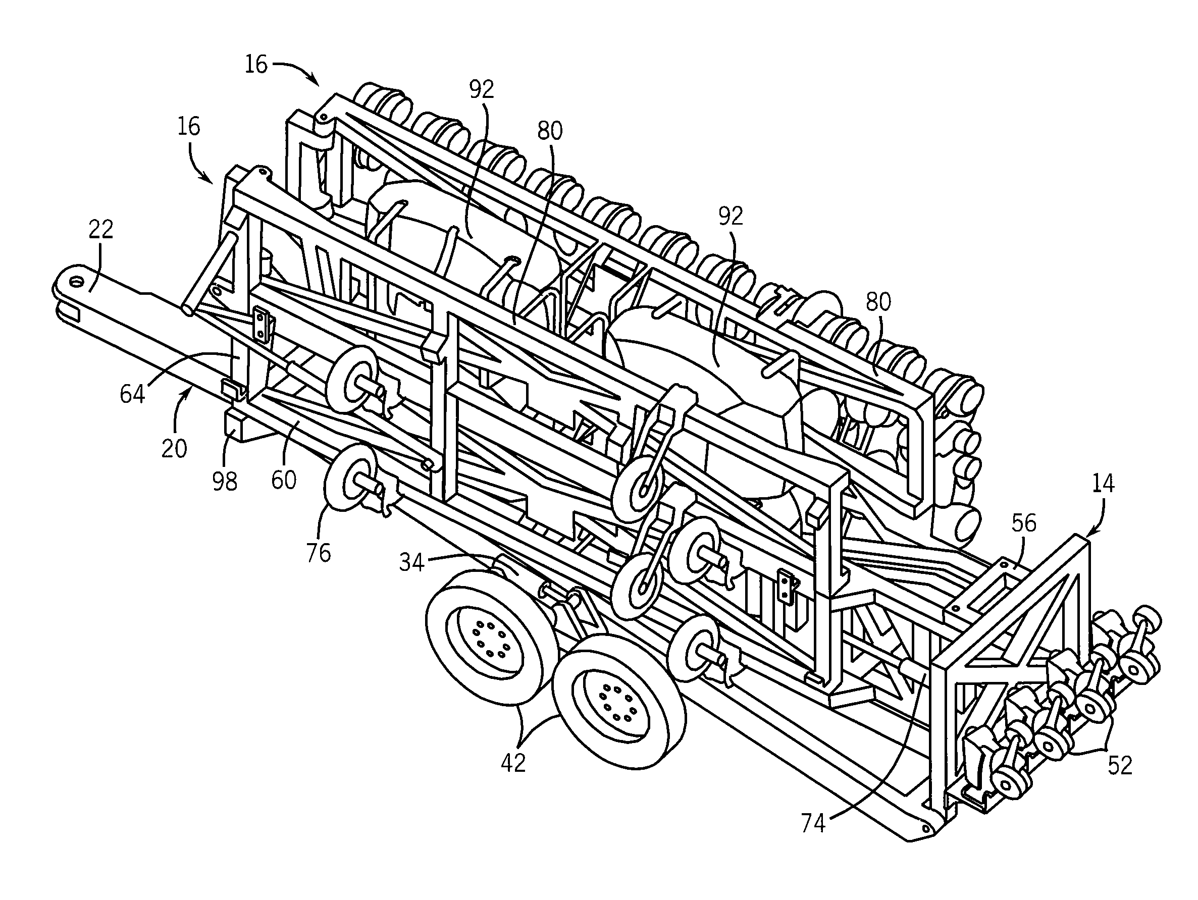
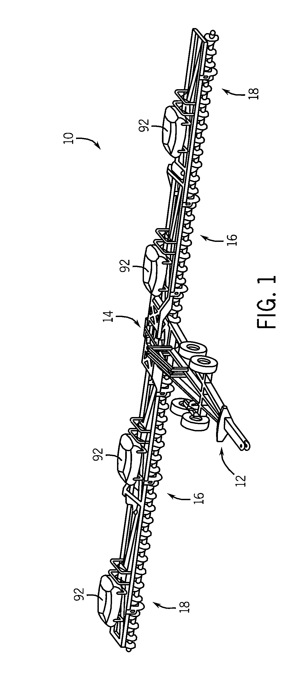
[0021]A foldable frame implement 10 according to one embodiment of the invention is shown in FIG. 1. The implement generally consists of a main frame assembly 12, a central frame member 14, inner wing members 16, and outer wing members 18. As will be described, several pivoting connections are used to interlink these components to allow the implement 10 to be folded from the extended in-field position shown in FIG. 1 to the folded, transport position shown in FIG. 6. While the foldable implement is not limited to any particular size, in one preferred embodiment, the implement has a width of 90 feet. In another embodiment, the implement has a width of 120 feet. In yet another embodiment, the implement has a width of 150 feet, and in a further embodiment, the implement has a width of 180 feet. It is also contemplated that the implement may have a width different from those listed above, including a width greater than 180 feet.

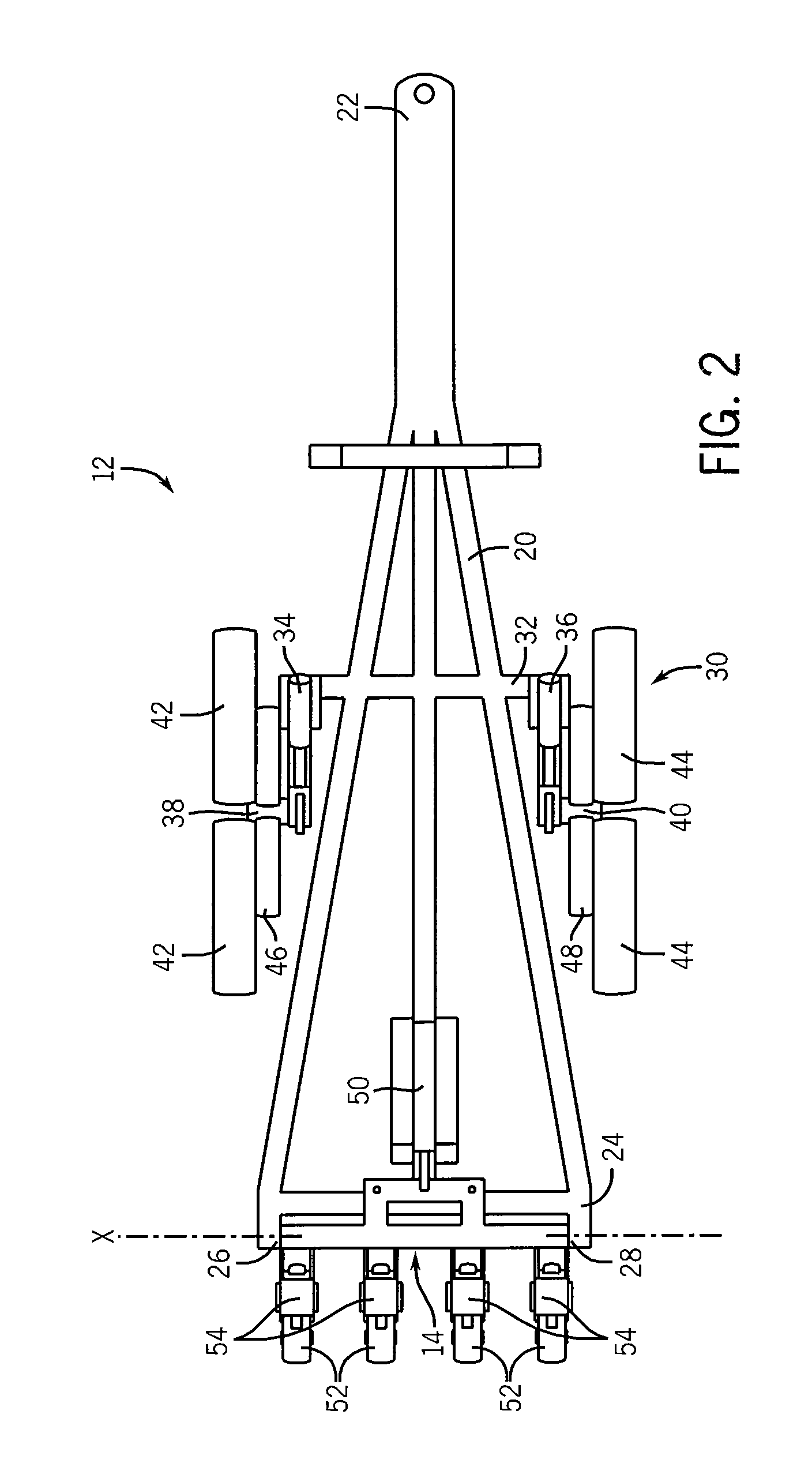
[0022]With additional reference to FIG. 2, the main frame a...


PUM


Abstract

A foldable implement frame is foldable about multiple axes to provide a compactly folded implement. The implement is foldable from a wide, field working position to a relatively narrow position for transport between fields, along roadways, and through field gates or storage doors. The frame is generally comprised of a center frame section that may be hitched to a prime mover, a pair of inner frame sections, and a pair of outer frame sections. The outer frame sections may be folded about their connections to the inner frame sections, and the inner frame sections are foldable about their connections to the central frame section. The central frame section may be rotated to rotate the inner and outer frame sections forward to an upright position, and the inner and outer frame sections may then be folded forward to fold the frame into a narrow position for transport and / or storage.

Description

BACKGROUND AND SUMMARY OF THE INVENTION[0001]The present invention is directed to farm implements and, more particularly, to a foldable implement frame having several frame elements that are foldable about various folding axes to provide a relatively compact arrangement for transport and stowage of the implement.[0002]Conventional farm implements, such as planters and seeders, generally consist of a center frame that can be hitched to a tractor or other prime mover, and wing booms mounted to opposed sides of the center frame. Depending on the type of implement, row units, scrapers, coulters, and other tools are mounted to the center frame and the wing booms. The overall width of the wing booms and center frame is being increased to provide more space to mount more tools. Such “wider” implements reduce the time necessary to work a field surface, such as planting a crop or tilling up crop residue.[0003]So that such wide implements can be transported over the road, the wing booms may b...

Claims


Application Information

Patent Timeline
Patent Type & Authority Patents(United States)
IPC IPC(8): A01B49/00
CPCA01B73/02A01B73/048A01B73/065
Inventor ADAMS, BRIANWENDTE, KEITH W.
Owner CNH IND AMERICA LLC
Why Eureka
Try Eureka