Sliding door apparatus

Active Publication Date: 2005-07-05
FUJI ELECTRIC CO LTD
View PDF4 Cites 35 Cited by
  • Summary
  • Abstract
  • Description
  • Claims
  • Application Information

AI Technical Summary

Benefits of technology

[0012]In the present invention, the guide roller is provided for restricting an upward movement of the side sliding door in addition to the door roller suspended from the door rail for supporting a downward load applied to the side sliding door. The gap between the guide roller and the ceiling of the door rail is set to be smaller than that between the door rail and the door roller. In the present invention, when a passenger applies a lateral load to the side sliding door and the door roller move upward along a curved bottom of the door rail, the guide roller contacts the ceiling of the door rail before the door roller contacts the ceiling of the door rail. Therefore, it is possible to prevent the door roller from becoming stuck when the door roller contacts the bottom of the door rail and the ceiling of the door rail

Problems solved by technology

If there is no gap, the door rollers 3 are stuck in the door rail 2, thereby making it difficult to open and close the entrance.
As described above, if the gap G is too small, the door rollers 3 are stuck, and it is difficult to open and

Method used


Image

  • Sliding door apparatus
  • Sliding door apparatus
  • Sliding door apparatus

Examples


Embodiment Construction

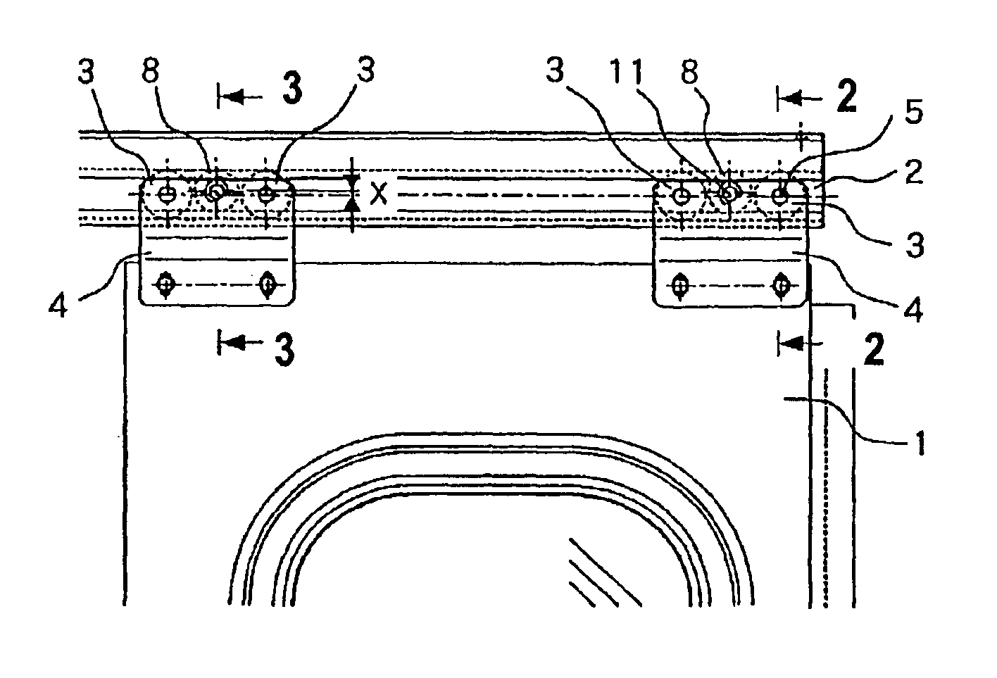
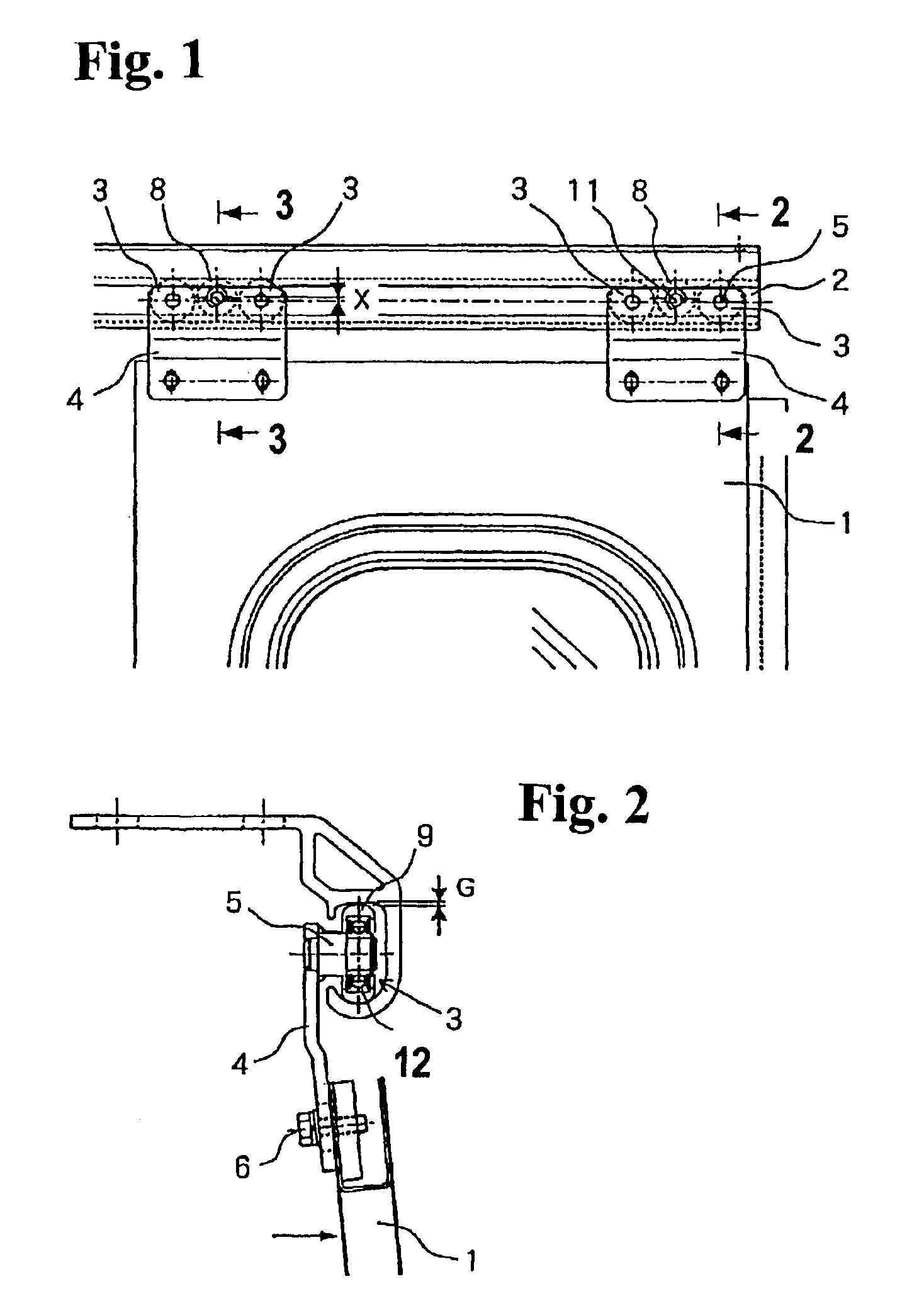
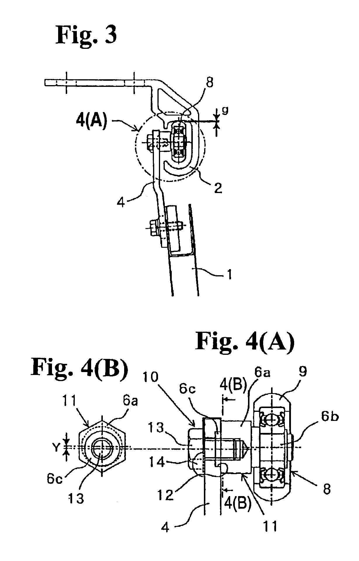
[0023]Hereunder, embodiments of the present invention will be explained with reference to the accompanying drawings. FIG. 1 is a front view showing an essential part of a left side sliding door of a double-hinged side sliding door apparatus according to the present embodiment. FIG. 2 is a sectional view taken along line 2—2 in FIG. 1, and FIG. 3 is a sectional view taken along line 3—3 in FIG. 1. FIG. 4(A) is an enlarged view of a section 4(A) shown in FIG. 3, and FIG. 4(B) is a sectional view taken along line 4(B)—4(B) in FIG. 4(A). It should be noted that components corresponding to those in the conventional apparatus shown in FIG. 5 and FIG. 6 are denoted by the same reference numerals.

[0024]In FIGS. 1 to 4, the present embodiment differs from the conventional apparatus in that a guide roller 8 is provided adjacent to and between two door rollers 3 attached to each of door hangers 4. The guide roller 8 is disposed at a location higher than the door rollers 3 by a distance X.

[0025...


PUM


Abstract

A side sliding door apparatus for an electric railcar includes a side sliding door suspended from a horizontal door rail with a C-shape cross-section. The side sliding door is capable of moving freely via a door roller, and a gap is formed between the door roller and a ceiling of the door rail. A guide roller with a smaller diameter than that of the door roller is provided adjacent to the door roller. A gap between the guide roller and the ceiling of the door rail is set to be smaller than that between the door roller and the ceiling of the door rail. Preferably, a gap adjusting mechanism is provided for adjusting the gap between the guide roller and the ceiling of the door rail.

Description

BACKGROUND OF THE INVENTION AND RELATED ART STATEMENT[0001]The present invention relates to a sliding door apparatus in an electric railcar for opening and closing a sliding door at an entrance of the electric railcar. In particular, the present invention relates to a structure for supporting the sliding door through suspension.[0002]Japanese Patent Publication (Kokai) No. 2000-142392 has disclosed a side sliding door apparatus for an electric railcar. As shown in FIGS. 5 and 6, such a conventional sliding door apparatus has a structure for supporting a side sliding door through suspension. FIG. 5 is a front view showing an essential part of the side sliding door, and FIG. 6 is a sectional view taken along line 6—6 in FIG. 5. The left-hand side in FIG. 6 corresponds to a vehicle compartment side. In FIGS. 5 and 6, a side sliding door 1 is suspended from a door rail 2 to move horizontally in FIG. 1 via door rollers 3. The door rollers 3 are mounted on each of door hangers 4 provided ...

Claims


Application Information

Patent Timeline
IPC IPC(8): E05D15/06B61D19/00
CPCE05D15/063E05D15/0652E05Y2201/638E05Y2201/688Y10T16/364E05Y2900/531Y10T16/35Y10T16/381E05Y2600/20
Inventor INAGE, AKIO
Owner FUJI ELECTRIC CO LTD
Why Eureka
Try Eureka