Voltage monitor and electrical storage device using the same
a voltage monitor and electrical storage technology, applied in the field of voltage monitors, can solve the problems of inconvenient switching, inability to accurately detect the divided voltage of each capacitor, and inability to adjust the voltage of the voltage monitor, so as to achieve the effect of easy detection of short-circuits and easy detection
- Summary
- Abstract
- Description
- Claims
- Application Information
AI Technical Summary
Benefits of technology
Problems solved by technology
Method used
Image
Examples
first exemplary embodiment
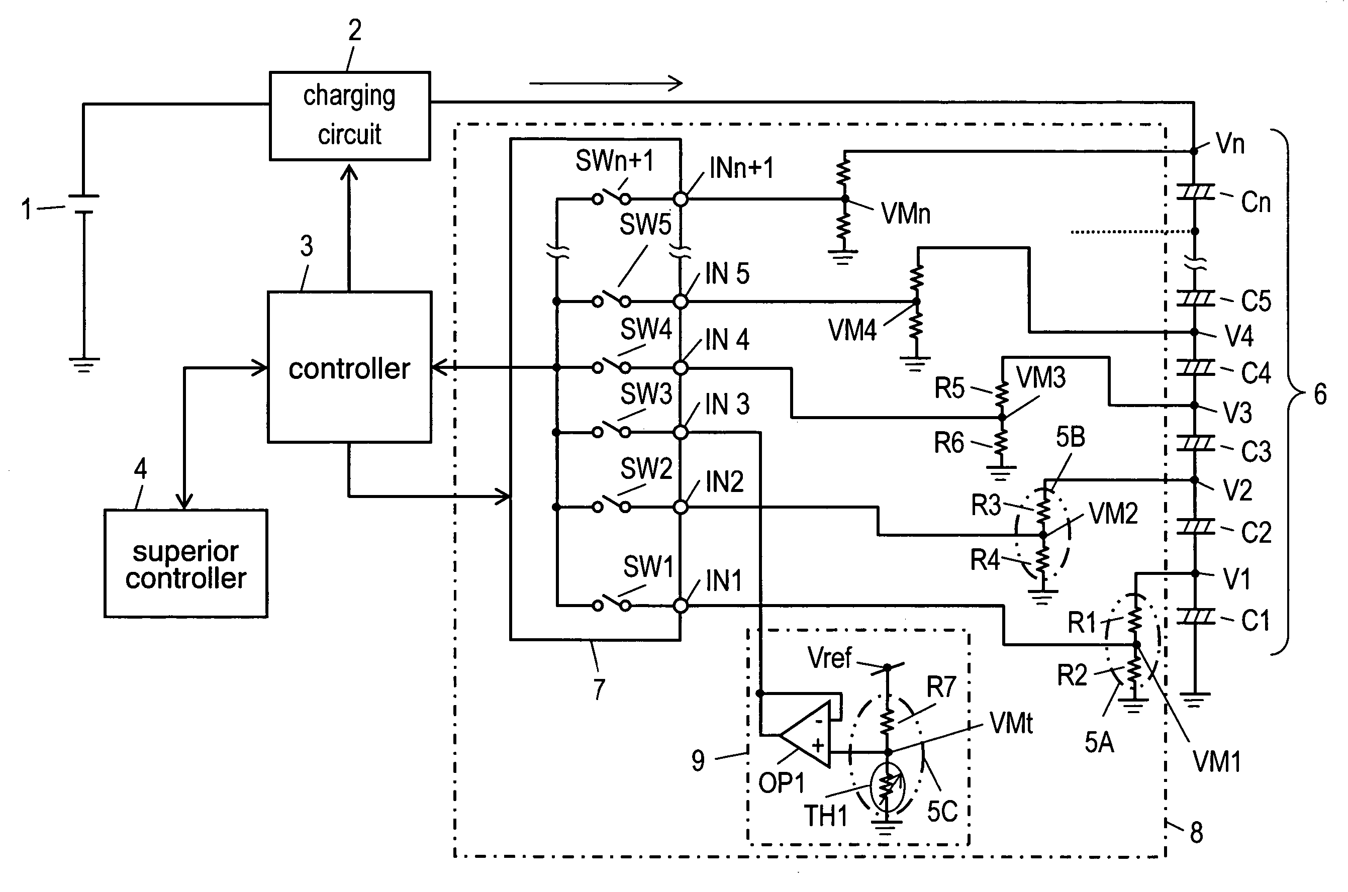
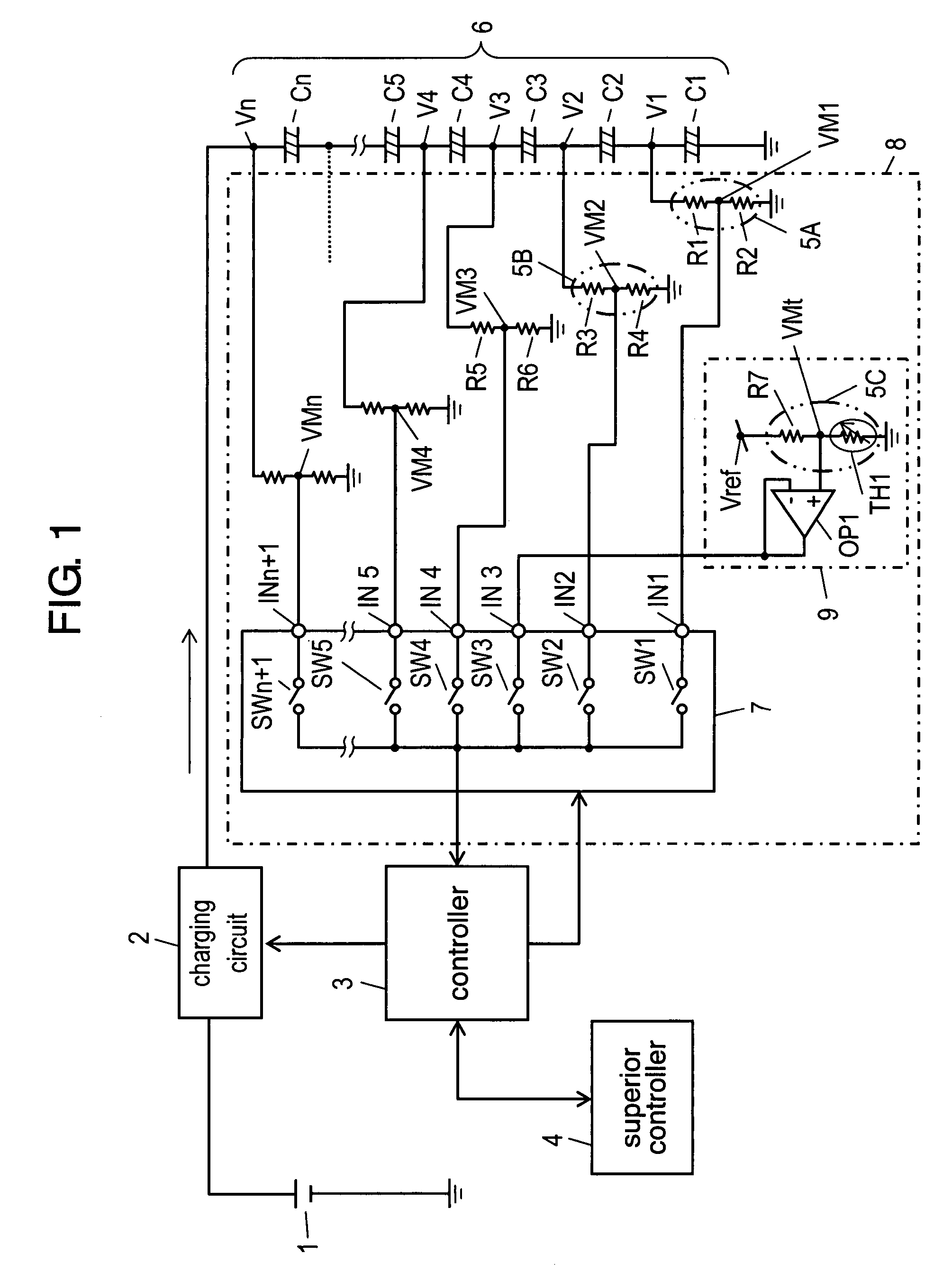
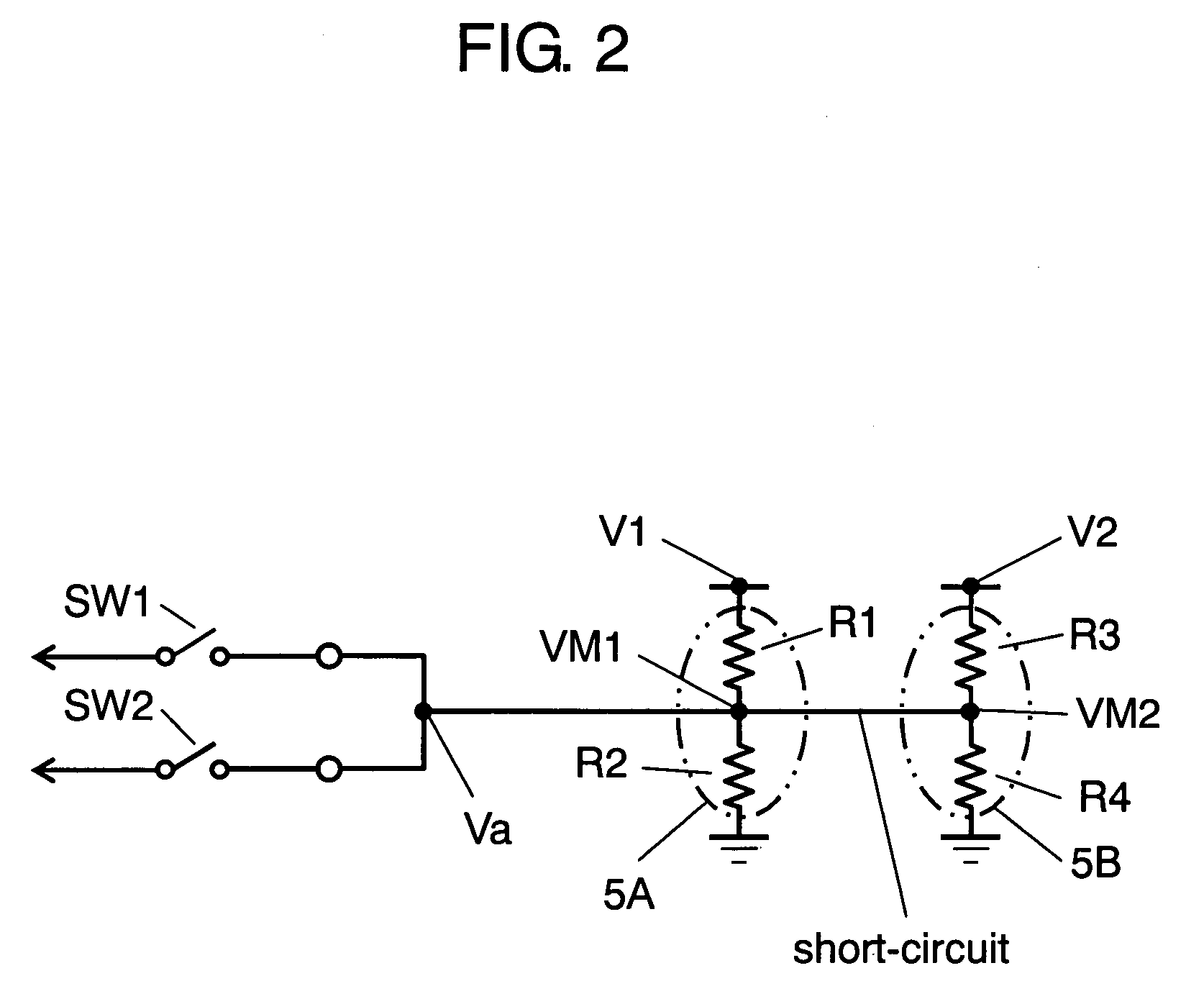
[0020]FIG. 1 is a circuit block diagram containing a voltage monitor in accordance with a first exemplary embodiment of the present invention. FIG. 2 is an equivalent circuit diagram when a short-circuit has occurred between input terminals of the voltage monitor of the present exemplary.
[0021]Main power supply 1, which is formed of a battery or a generator, is connected to charging circuit 2. Charging circuit 2 controls charging voltage and charging current at each predetermined value. Charging circuit 2 receives operation instructions to start or stop charging from controller 3. As described later, controller 3 controls whole of the voltage monitor, and communicates with superior controller 4 to determine the start and stop of charging.
[0022]Storage section 6 is formed of electrical double layer capacitors C1 through Cn (n represents the number of capacitors) connected in series. With the use of resistors R1 and R2, voltage-dividing section 5A as a first voltage-dividing section d...
second exemplary embodiment
[0057]FIG. 3 is a circuit diagram containing a voltage monitor in accordance with a second exemplary embodiment of the present invention. FIG. 4 is an equivalent circuit diagram when a short-circuit has occurred between an input terminal that receives the output of divided voltage at a divided voltage section and an input terminal that receives the output of temperature at a temperature-detecting section in the voltage monitor. FIGS. 5A through 5C are charts showing time-varying characteristics of the voltage of the voltage monitor. FIG. 5A shows time-varying characteristics of the voltage at a connecting point of capacitors under normal condition of the voltage monitor. FIG. 5B shows time-varying characteristics of the voltage at a connecting point of capacitors when a short-circuit has occurred between the input terminals under the condition where the output voltage of temperature at the temperature-detecting section is higher than the output of divided voltage at the voltage-divi...
third exemplary embodiment
[0074]FIG. 6 is a circuit diagram showing the temperature-detecting section of a voltage monitor in accordance with the third exemplary embodiment. FIG. 7 is a partial circuit diagram showing a state in which output of divided voltage is selected when a short-circuit has occurred between the input terminal that receives the output of divided voltage at a voltage-dividing section and the input terminal that receives the output of temperature at the temperature-detecting section in the voltage monitor.
[0075]The structure of the embodiment differs from the structure of FIG. 3 in the second embodiment in employing temperature-detecting section 9A having the circuit structure of FIG. 6. The rest of the structure is almost the same as that in the second embodiment; accordingly, like parts have same reference marks and in-detail description thereof will be omitted. The description below will be focused on the different section.
[0076]According to the structure of the second embodiment, divi...
PUM
 Abstract
Description
Claims
Application Information
 - R&D
- Intellectual Property
- Life Sciences
- Materials
- Tech Scout
- Unparalleled Data Quality
- Higher Quality Content
- 60% Fewer Hallucinations
Browse by: Latest US Patents, China's latest patents, Technical Efficacy Thesaurus, Application Domain, Technology Topic, Popular Technical Reports.
© 2025 PatSnap. All rights reserved.Legal|Privacy policy|Modern Slavery Act Transparency Statement|Sitemap|About US| Contact US: help@patsnap.com


