

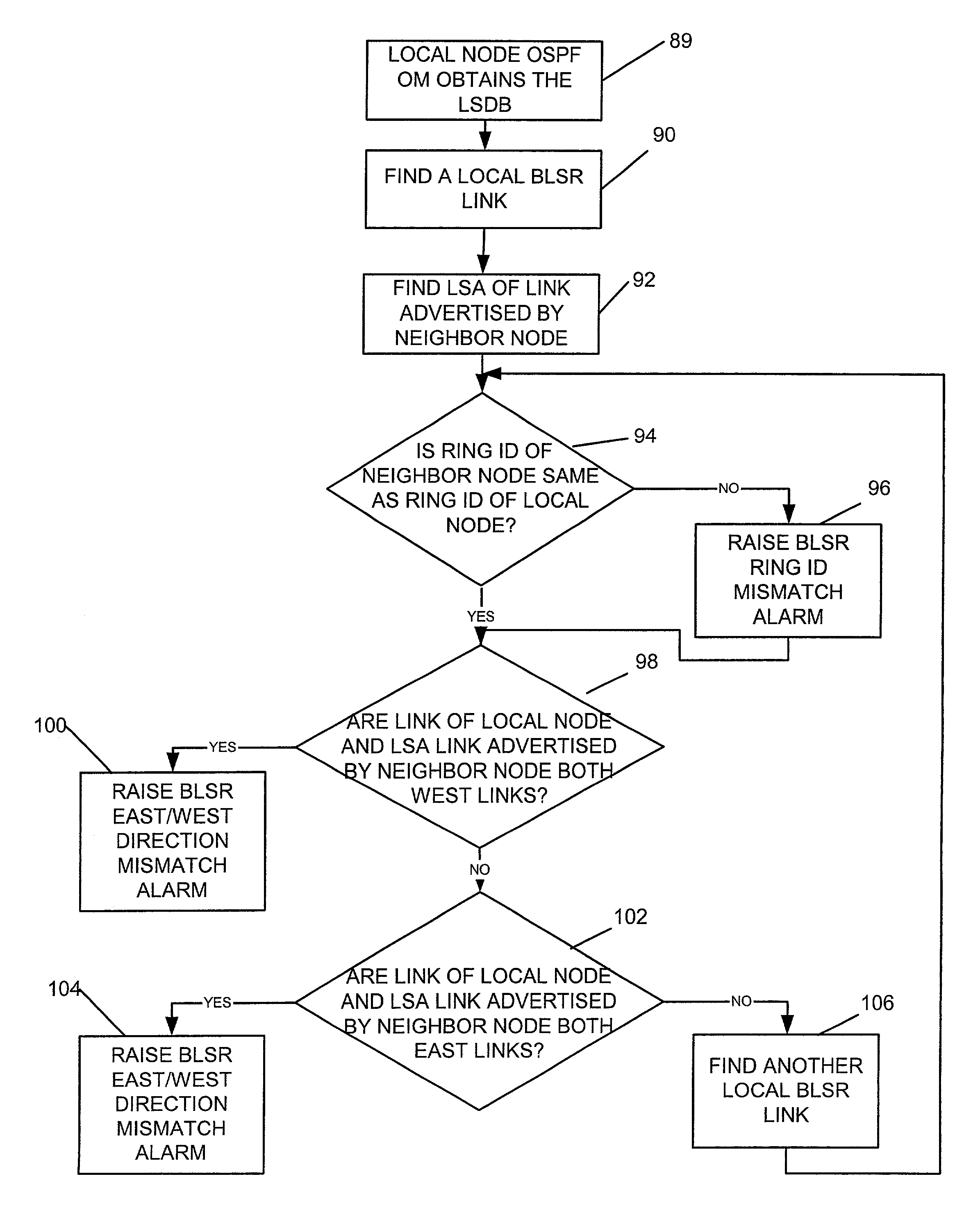
Method and system for detecting ring link provisioning mismatch
a technology of ring link and mismatch detection, applied in the field of automatic detection of ring link provisioning errors within the communications network, can solve problems such as user ignoran
- Summary
- Abstract
- Description
- Claims
- Application Information
AI Technical Summary
Benefits of technology
Problems solved by technology
Method used
Image

Examples
Embodiment Construction
[0017]The following description is presented to enable one of ordinary skill in the art to make and use the invention. Descriptions of specific embodiments and applications are provided only as examples and various modifications will be readily apparent to those skilled in the art. The general principles described herein may be applied to other embodiments and applications without departing from the scope of the invention. Thus, the present invention is not to be limited to the embodiments shown, but is to be accorded the widest scope consistent with the principles and features described herein. For purpose of clarity, details relating to technical material that is known in the technical fields related to the invention have not been described in detail.
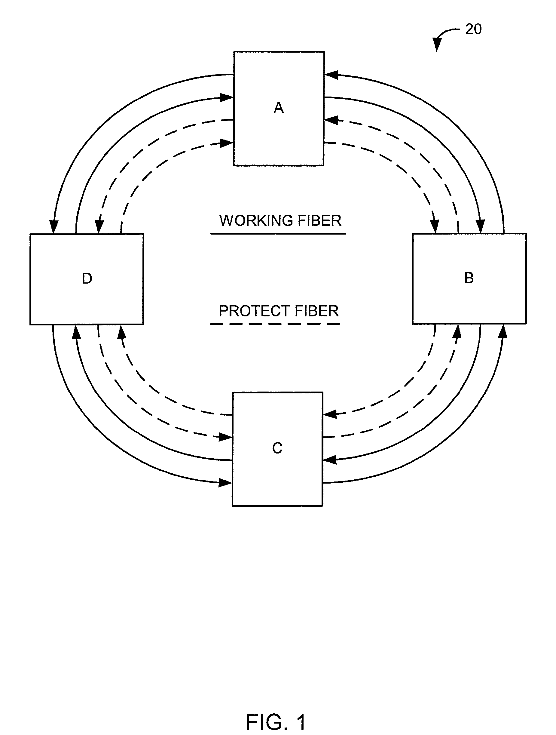
[0018]Referring now to the drawings, and first to FIG. 1, a four-fiber BLSR SONET ring is shown, and generally indicated at 20. The BLSR contains four nodes A, B, C, D. The BLSR may be used, for example, in the backbone of a long haul...
PUM
 Abstract
Description
Claims
Application Information