Caster skate apparatus

a caster and skate technology, applied in the field of caster skate equipment, can solve the problems of large riding space, large turning radius of skateboards, and the rider having to push the ground, and achieve the effects of convenient folding, convenient change of direction, and good portability

Inactive Publication Date: 2009-02-03
TASEM CO LTD
View PDF8 Cites 21 Cited by
  • Summary
  • Abstract
  • Description
  • Claims
  • Application Information

AI Technical Summary

Benefits of technology

[0021]The caster skate apparatus of the present invention has the following effects.
[0022]Firstly, the caster skate apparatus comprises a pair of boards interconnected by means of a flexible connector. In this case, both the boards can move independently by virtue of the flexible connector, to be repeatedly turned to the right and left. Accordingly, as the rider twists his / her ankles or turns his / her body to the right and left, the boards can be propelled with the ability to easily change direction by use of a propulsive force obtained in accordance with the rotating and rolling motions of rollers mounted on the undersides of the boards.
[0023]Secondly, the overall length of the connector is adjustable within a predetermined maximum value. This allows the rider to maneuver the caster skate apparatus more delicately, and to make a turn within a small turning radius. Therefore, the rider can ride the caster skate apparatus even in a narrow space and providing more exercise.
[0024]Thirdly, since the length adjustable connector enables the distance between the two boards to be adjusted within a predetermined range, the overall size of the caster skate apparatus can be adjusted to suit the body size of the rider.
[0025]Fourthly, the boards, interconnected by means of the flexible connector, are able to be conveniently folded, resulting in good portability.
[0026]Fifthly, as compared to the above-described prior art wherein two boards are inter-connected by means of an elastic element, the caster skate apparatus of the present invention can achieve a reduction in the turning radius of the boards, enabling delicate cornering maneuvers. Further, since the rider has to repeatedly change the relative positions of both feet placed on the two boards while maneuvering, the caster skate apparatus of the present invention can provide serious exercise.

Problems solved by technology

Disadvantages associated with the conventional skateboard include the fact that the skateboard rider has to push the ground with one foot to achieve additional speed or propulsion when the propulsion of the skateboard is achieved by the rolling of the rollers on the ground.
Also, the skateboard inevitably requires a large turning radius when changing the direction of travel or making a U-turn.
This results in the need of a large riding space and the rider derives no pleasure from being able to perform delicate movements while riding.
The above-described prior art, however, has the following several problems due to the fact that the two boards are interconnected by use of the elastic element.
Firstly, the two boards, bound with each other via the elastic element, require a large turning radius to change the direction of travel to the left and right or to make a U-turn.
Accordingly, changing the direction of travel of the boards has the need of a large space and cannot be rapidly performed.
Secondly, such a large turning radius as mentioned above makes it impossible for the skateboard rider to delicately maneuver the skateboard.
Fourthly, the prior art skateboard has a fixed length.
In this case, the skateboard may often be unsuitable for the rider's body size.
For example, the skateboard may be too big for small-sized people or too small for large-sized people to conveniently maneuver the skateboard.

Method used


Image

  • Caster skate apparatus
  • Caster skate apparatus
  • Caster skate apparatus

Examples


Embodiment Construction

[0036]Now, preferred embodiments of the present invention will be explained in detail with reference to the accompanying drawings.

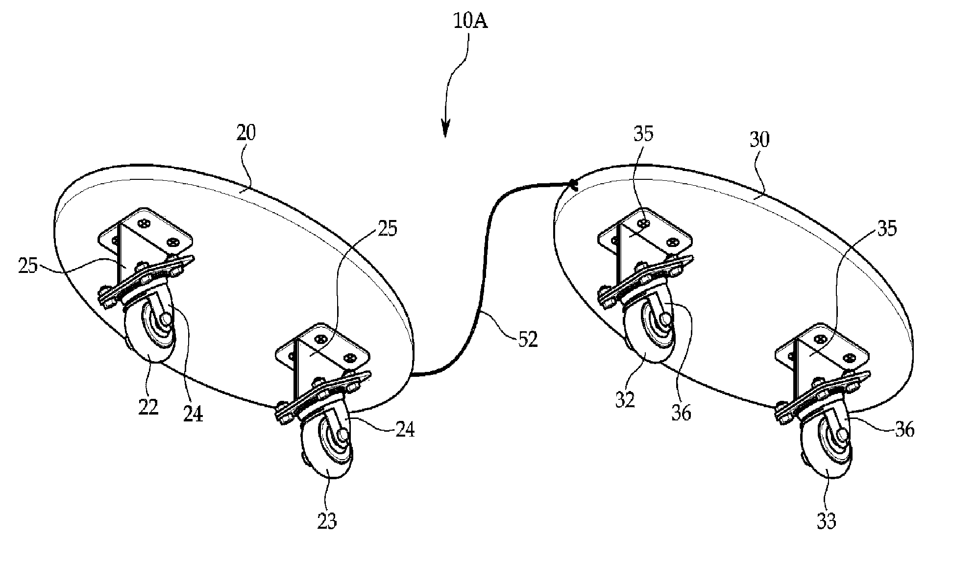
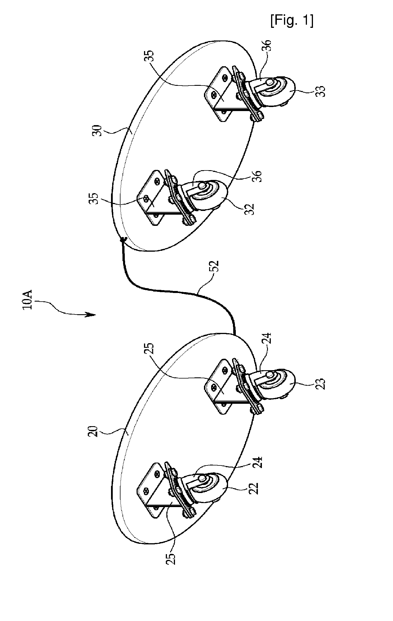
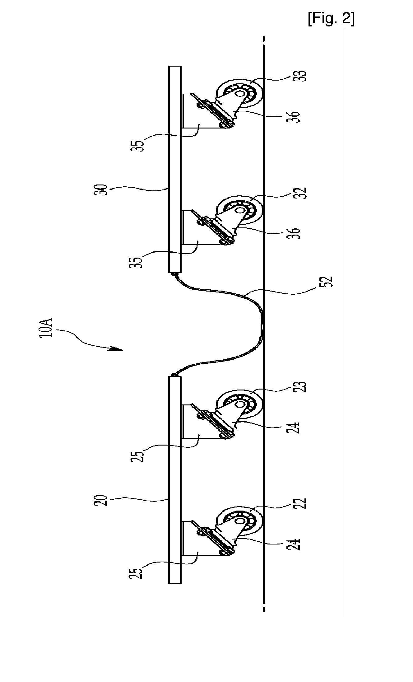
[0037]FIGS. 1 and 2 illustrate a caster skate apparatus 10A in accordance with a first embodiment of the present invention. FIG. 3 is a view illustrating the use of the caster skate apparatus in accordance with the present invention. As shown in FIG. 3, the caster skate apparatus 10A is designed to be propelled as a rider turns his / her body to the right and left. In this case, both legs of the rider serve as rotating axes Z1 and Z2. The caster skate apparatus 10A is also able to change the direction of travel easily. Thus, the caster skate apparatus 10A of the present invention effectively increases the enjoyment of the rider.

[0038]As shown in FIGS. 1 and 2, the caster skate apparatus 10A comprises: a front board 20 to support one foot thereon; a rear board 30 arranged at the rear side of the front board 20 to support the other foot thereon; and a flexibl...


PUM


Abstract

Disclosed herein is a caster skate apparatus to be propelled in a direction changeable manner by use of rider's both feet. The apparatus comprises front and rear boards (20, 30) to support both feet thereon, first and second rollers (22, 23) mounted to the underside of the front board at front and rear locations by a predetermined distance, third and fourth rollers (32, 33) mounted to the underside of the rear board at front and rear locations by a predetermined distance, a flexible connector (52) having a predetermined length and connected at opposite ends thereof to the front and rear boards to allow the front and rear boards to independently move within a predetermined range. A rotating center of each of the first and third rollers is spaced apart from an axis, having a predetermined inclination angle with respect to undersides of the respective boards, by a predetermined distance.

Description

TECHNICAL FIELD[0001]The present invention relates to a caster skate apparatus which can achieve easy propulsion and change in the direction of travel as a rider twists his / her ankles or turns his / her body to the right and left, thereby increasing the enjoyment of the rider.BACKGROUND ART[0002]As a representative example of sporting goods wherein a rider places both feet on the board deck while coasting and maneuvering, skateboards are well known.[0003]Now, considering the basic configuration of a conventional skateboard, it includes an elongated oval deck having an area to place both feet thereon, and a pair of rollers rotatably mounted on the underside of the deck at front and rear locations, so that they can roll along the ground.[0004]Disadvantages associated with the conventional skateboard include the fact that the skateboard rider has to push the ground with one foot to achieve additional speed or propulsion when the propulsion of the skateboard is achieved by the rolling of ...

Claims


Application Information

Patent Timeline
Patent Type & Authority Patents(United States)
IPC IPC(8): A63C17/01
CPCA63C17/0033A63C17/01A63C17/012A63C17/016A63C17/12A63C2203/02A63C2203/40
Inventor CHOI, YNOK
Owner TASEM CO LTD
Why Eureka
Try Eureka