Bumper structure

a bumper and structure technology, applied in the direction of bumpers, vehicle components, pedestrian/occupant safety arrangements, etc., can solve the problem of not describing the use of multiple (particularly, multiple types of) collision detection sensors

Inactive Publication Date: 2009-02-03
TOYOTA JIDOSHA KK
View PDF30 Cites 13 Cited by
  • Summary
  • Abstract
  • Description
  • Claims
  • Application Information

AI Technical Summary

Benefits of technology

[0006]It is an object of the invention to provide a bumper structure that stabilizes the detection performance of multiple detecting means (or multiple types of detecting means).
[0009]In the structure described above, the multiple detecting means are provided outboard of the reinforced portion. In addition, the reinforcement portion suppresses deformation of the bumper reinforcement when a load or the pressure is applied to the bumper. Accordingly, the load or the pressure applied to the bumper can be appropriately applied to the multiple detecting means. Thus, the detection performance of the multiple detecting means can be stabilized.
[0012]In the bumper structure described above, the first detecting means is provided outboard of the reinforced portion of the bumper reinforcement, and the second detecting means is provided directly outboard of the first detecting means or provided outboard of the first detecting means with the rigid body interposed between the first detecting means and the second detecting means. Therefore, when the load or the pressure is applied to the bumper, the load or the pressure applied to the bumper is appropriately applied from the second detecting means to the first detecting means. Thus, the detection performance of the first detecting means and the second detecting means can be stabilized.

Problems solved by technology

However, this publication does not describe usage of multiple (particularly, multiple types of) collision detection sensors.

Method used


Image

  • Bumper structure
  • Bumper structure
  • Bumper structure

Examples


Embodiment Construction

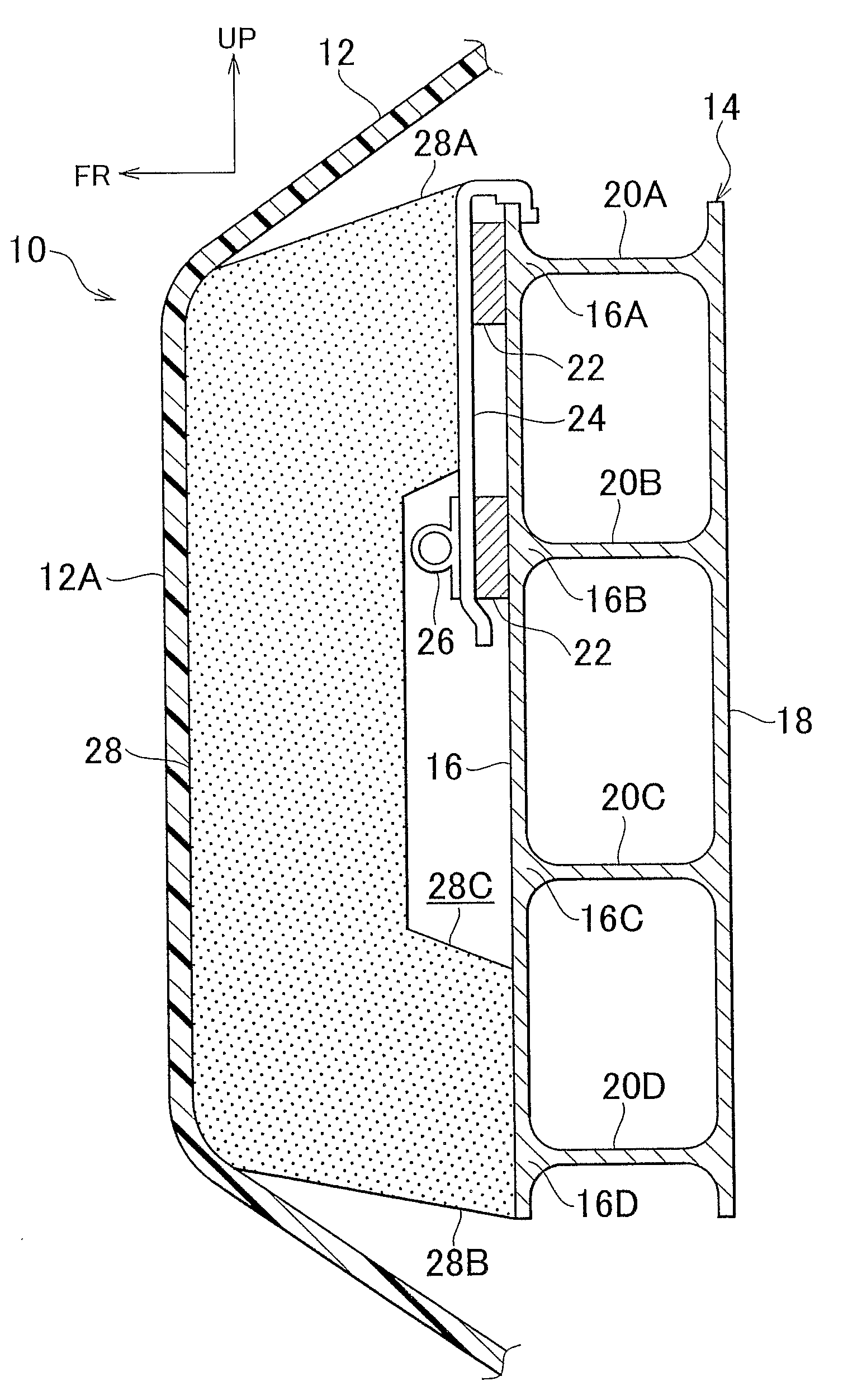
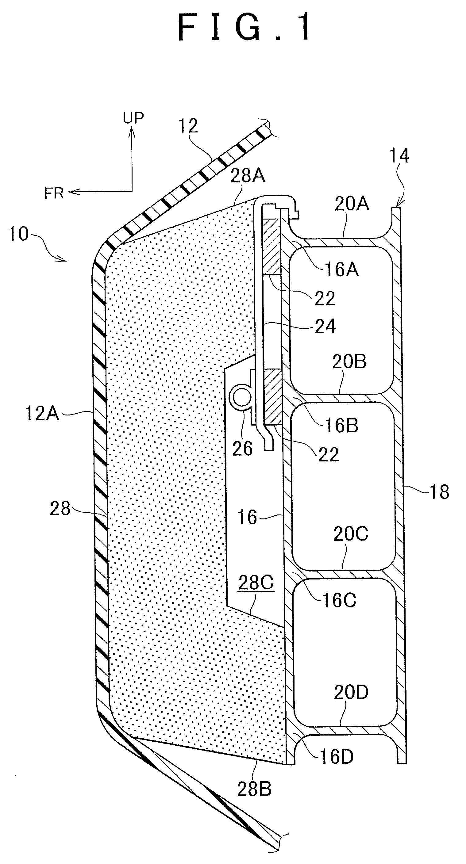
[0016]FIG. 1 illustrates the cross-sectional view of a bumper 10 according to an embodiment of the invention, viewed from the left side of a vehicle. In FIG. 1, the arrow FR indicates the front of a vehicle, and the arrow UP indicates the top-side of the vehicle.

[0017]The bumper 10 according to the embodiment is provided at the front-end of the vehicle, and extends along the front of the vehicle. Both ends of the bumper 10 are curved toward the rear of the vehicle.

[0018]The bumper 10 is provided with a bumper cover 12 that has a substantially U-shaped cross section. The bumper cover 12 configures the design of the bumper 10. The bumper cover 12 extends along the front of the vehicle. Both ends of the bumper cover 12 are curved toward the rear of the vehicle in accordance with the curvature of the both ends the bumper 10.

[0019]A bumper reinforcement 14 is provided inside of the bumper cover 12, at the position closer to the rear of the vehicle than a position, at which there is no bu...


PUM


Abstract

In a bumper, a touch sensor and a load detection sensor detect a load applied to the bumper in the event of a head-on collision, when pressed by an absorber. The touch sensor and the load detection sensor are provided in front of reinforced portions of a front wall of a bumper reinforcement. The touch sensor is provided in front of the load detection sensor with a load transfer plate interposed the touch sensor and the load detection sensor. In addition, in the event of a head-on collision, deformation of the front wall is suppressed by the reinforced portions and the load is appropriately applied to the touch sensor and the load detection sensor, and the load is appropriately applied from the touch sensor to the load detection sensor. Thus, the detection performance of the touch sensor and the load detection sensor can be stabilized.

Description

BACKGROUND OF THE INVENTION[0001]1. Field of the Invention[0002]The invention relates to a structure of a bumper for a vehicle.[0003]2. Description of the Related Art[0004]Japanese Patent Application Publication No. JP-A-2000-225907 describes a bumper structure in which a collision detection sensor is provided between a shock absorber and a reinforcement member of a bumper.[0005]However, this publication does not describe usage of multiple (particularly, multiple types of) collision detection sensors.SUMMARY OF THE INVENTION[0006]It is an object of the invention to provide a bumper structure that stabilizes the detection performance of multiple detecting means (or multiple types of detecting means).[0007]A first aspect of the invention relates to a bumper structure. The bumper structure includes a bumper reinforcement provided in a bumper of a vehicle; a reinforced portion that is formed within the bumper reinforcement and that reinforces the bumper reinforcement; and multiple detec...

Claims


Application Information

Patent Timeline
Patent Type & Authority Patents(United States)
IPC IPC(8): B60R19/48
CPCB60R19/483B60R21/34B60R19/03B60R2019/186
Inventor TAKAHASHI, HIROYUKI
Owner TOYOTA JIDOSHA KK
Why Eureka
Try Eureka