Run channel structure

a technology of channel structure and run channel, which is applied in the direction of wing accessories, transportation and packaging, wing arrangements, etc., can solve the problems of door glass stopping and unpleasant strike sound, and achieve the effect of reducing the ascent speed of door glass, reducing the glass strike, and reducing the reaction for

Inactive Publication Date: 2009-02-10
HONDA MOTOR CO LTD
View PDF12 Cites 33 Cited by
  • Summary
  • Abstract
  • Description
  • Claims
  • Application Information

AI Technical Summary

Benefits of technology

[0009]When the door glass abuts on the inner lip, the door glass presses the inner lip towards the inner wall to thereby cause the distal end portion of the inner lip to press the upper lip. By the distal end portion of the inner lip thus pressing the upper lip, a reaction force of the upper lip is applied to the distal end portion of the inner lip to thereby make relatively large a reaction force of the inner lip to be applied to the door glass. By virtue of such a relatively large reaction force of the inner lip, an ascent speed of the door glass is satisfactorily reduced. Thus, an upper edge of the door glass relatively slowly abuts on the peak portion of the run channel structure while a reduced glass strike sound of the door glass is produced. The term “glass strike sound” as used herein means a sound produced when the upper edge portion of the door glass abuts on the peak portion of the run channel structure.
[0010]Preferably, the upper lip, the inner wall and the peak portion jointly define a hollow cross-sectional portion of generally triangular configuration. Namely, the upper lip is one side of the hollow cross-sectional portion of the generally triangular configuration with opposite ends of the upper lip supported. With this arrangement, a relatively large reaction force of the upper lip is securely produced when the distal end portion of the inner lip presses the upper lip. Such a relatively large reaction force of the upper lip is applied to the distal end portion of the inner lip to thereby cause the inner lip to produce a sufficient reaction force to be applied to the door glass. The application of the reaction force of the inner lip to the door glass satisfactorily reduces the ascent speed of the door glass with the result that the upper edge portion of the door glass relatively slowly abuts on the peak portion of the run channel structure.
[0011]Desirably, after the distal end portion of the inner lip presses the upper lip, the upper edge portion of the door glass abuts on the upper lip. Accordingly, it becomes possible to reduce the ascent speed of the door glass through the two steps, thereby causing the upper edge portion of the door glass to relatively slowly abut on the peak portion of the run channel structure. In addition, since the upper lip forms the one side of the hollow cross-sectional portion of the generally triangular configuration, an internal pressure within the hollow cross-sectional portion increases when the distal end portion of the inner lip presses the upper lip. This enables the upper lip to act as a cushion more effectively for producing a relatively large reaction force. Therefore, the ascent speed of the door glass is further satisfactorily reduced by the upper lip when the door glass abuts on the upper lip, with the result that the upper edge of the door glass relatively slowly abuts on the peak portion of the run channel structure.
[0012]Preferably, the hollow cross-sectional portion has an air releasing hole through which an inner space of the hollow cross-sectional portion communicates with the air. Thus, the internal pressure within the hollow cross-sectional portion can be easily adjusted and hence the reaction force of the upper lip and the reaction force of the inner lip to be applied to the door glass can be adjusted. This enables the satisfactory adjustment of the ascent speed of the door glass, such that the upper edge of the door glass abuts on the peak portion of the run channel structure at a preferable speed.
[0013]Preferably, the inner lip is formed to provide a greater size than the outer lip so as to facilitate an adjustment of a reaction force of the inner lip to be applied to the door glass when the door glass abuts on the inner lip. Thus, the inner lip can be relatively easily varied in configuration for easy adjustment of the reaction force of the inner lip to be applied to the door glass. By virtue of the inner lip, the ascent speed of the door glass can be satisfactorily adjusted, such that the upper edge of the door glass abuts on the peak portion of the run channel structure at a preferable speed.

Problems solved by technology

Such an excessive load is detected to thereby stop an operation of an electric motor with the result that the door glass stops at a closed position (i.e., at an uppermost position).
Such an excessive load is detected to thereby stop an operation of an electric motor with the result that the door glass stops at a closed position (i.e., an uppermost position).
As for the run channel, a problem arises that the window regulator raises and strikes the upper edge of the door glass onto the peak portion of the run channel at a predetermined speed whereupon an unpleasant strike sound is produced.

Method used


Image

  • Run channel structure
  • Run channel structure
  • Run channel structure

Examples


Embodiment Construction

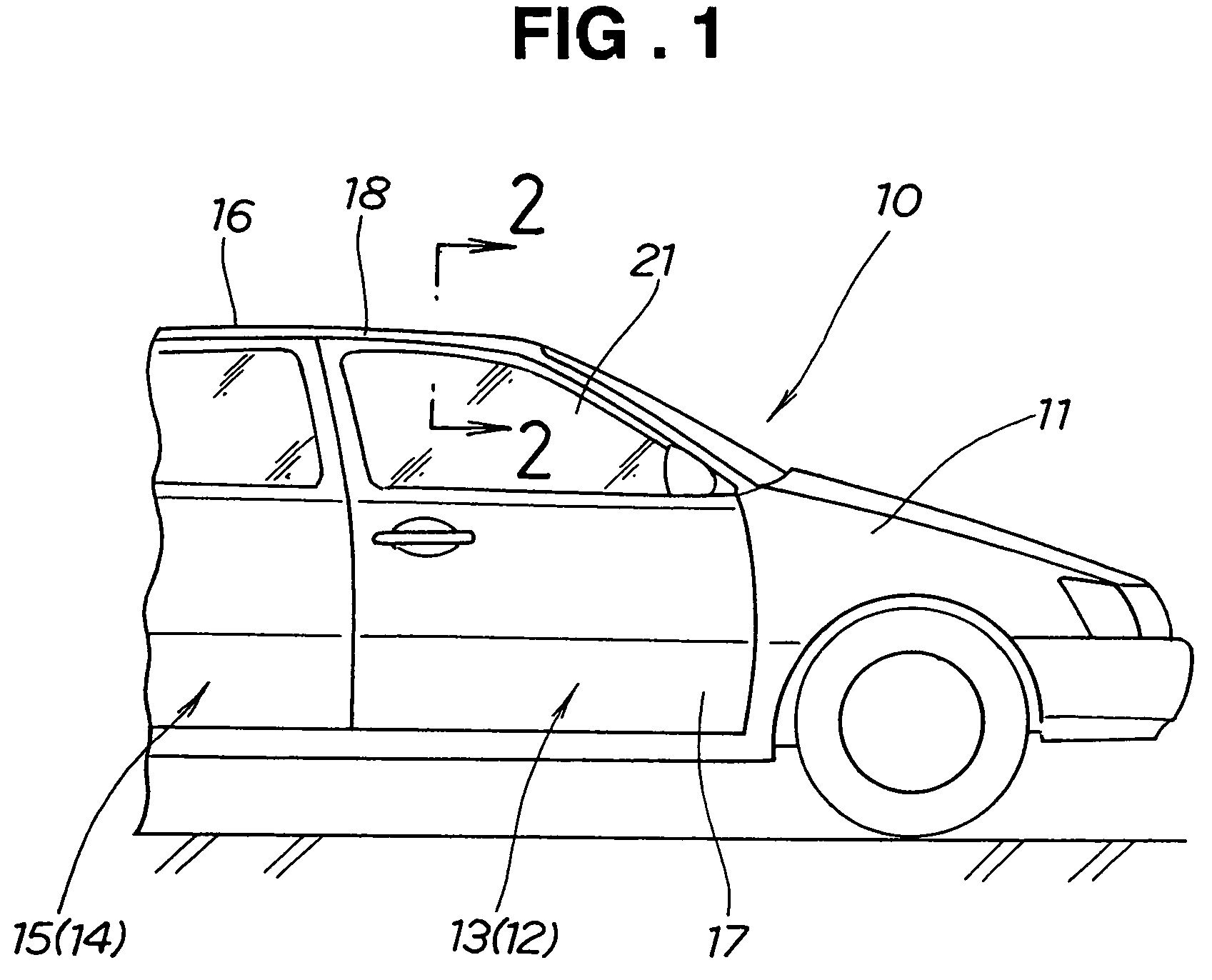
[0022]A vehicle 10 shown in FIG. 1 includes a vehicle body 11 equipped with left and right front sash doors 12, 13 and left and right rear sash door 14, 15. The vehicle body 11 has a roof 16 disposed over the left and right front sash doors 12, 13 and the left and right rear sash doors 14, 15.

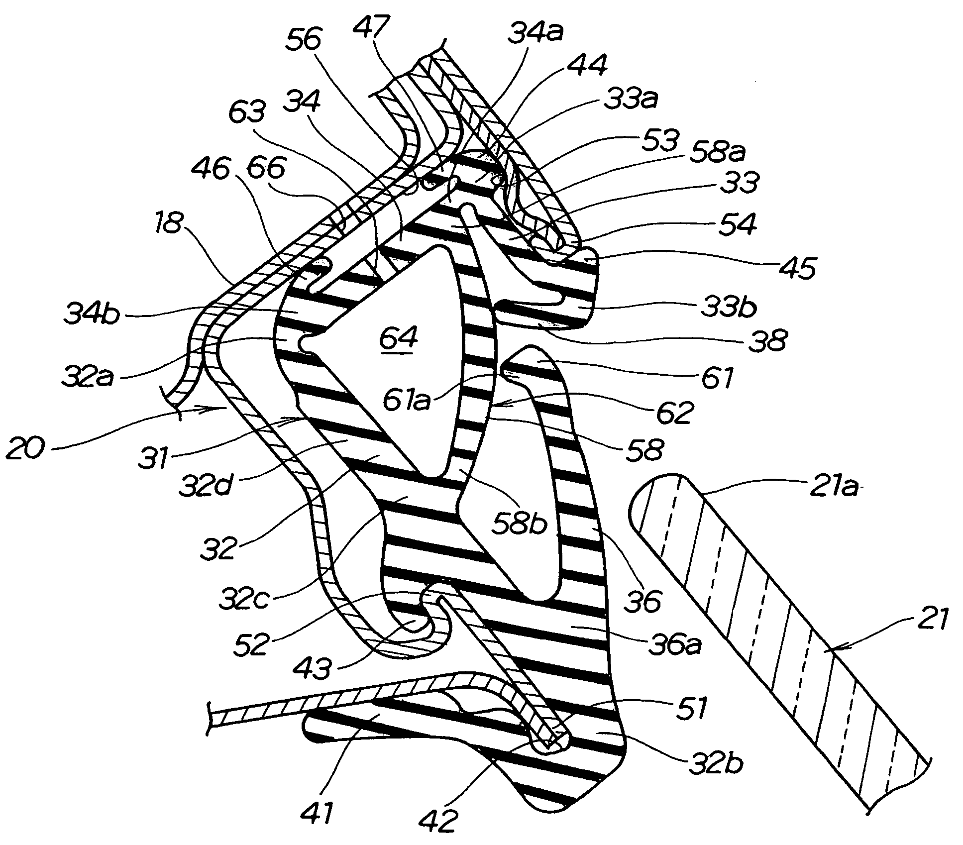
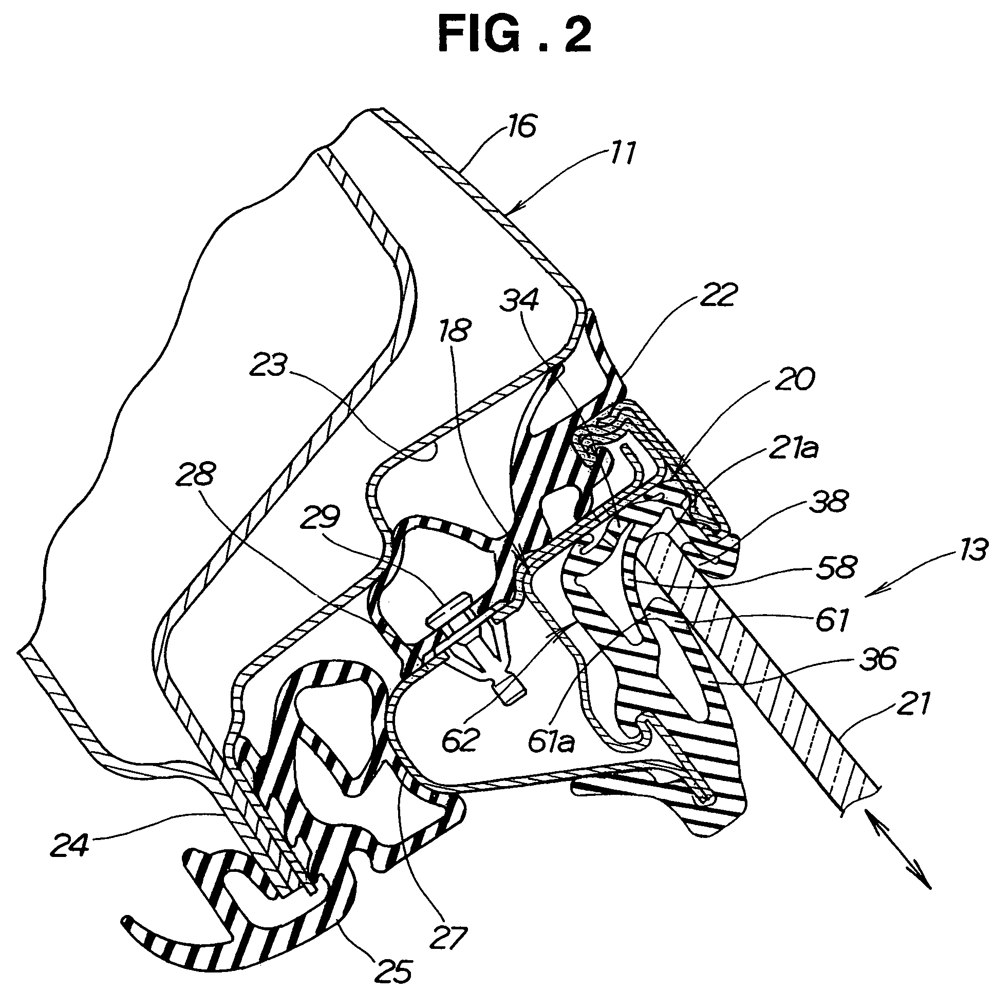
[0023]The right front sash door 13 includes a door body 17, a sash body 18 provided on an upper part of the door body 17, and a run channel structure 20 (see FIG. 2) provided in the sash body 18. The right front sash door 13 also includes a door glass 21.

[0024]It is to be noted that the left and right front sash doors 12, 13 have the same structure and are symmetrically disposed while the left and right rear sash doors 14, 15 have the same structure and are symmetrically disposed.

[0025]FIG. 2 shows the right front sash door 13 in a closed position.

[0026]The sash body 18 of the right front sash door 13 is equipped with a weatherstrip 22 and the run channel structure 20. The vehicle body 11 has a...


PUM


Abstract

A run channel in an automobile door includes a U-shaped run channel body. An inner lip extends from a bottom end portion of an inner wall of the run channel body towards a peak portion. An upper lip is formed above the inner lip and extends from an intermediate portion of the inner wall to the peak portion. When a door glass abuts on the inner lip, the door glass presses the inner lip towards the inner wall to cause a distal end portion of the inner lip to press on the upper lip, whereby a reaction force of the upper lip is applied to the distal end portion of the inner lip. The inner lip in turn produces a reaction force slowing upward movement of the door glass, causing its upper edge to slowly abut on the peak portion of the run channel, thus reducing a glass striking sound.

Description

FIELD OF THE INVENTION[0001]The present invention relates generally to a run channel structure and, in particular, to a run channel structure including a run channel body for receiving an edge portion of a door glass, and inner and outer lips provided to the run channel body.BACKGROUND OF THE INVENTION[0002]Door glass ascent / descent systems include window regulators for moving door glasses of vehicles upward or downward. The door glass is moved upward by the window regulator for closing a window of a vehicular door. When the door glass is moved upward and then an upper edge of the door glass hits a run channel, the door glass is prevented from moving further upward. At this time, a load exceeding a threshold level is applied to the window regulator. Such an excessive load is detected to thereby stop an operation of an electric motor with the result that the door glass stops at a closed position (i.e., at an uppermost position).[0003]The above run channel is attached to a window sash...

Claims


Application Information

Patent Timeline
Patent Type & Authority Patents(United States)
IPC IPC(8): E06B7/16E06B3/44
CPCB60J10/04B60J10/74
Inventor WATANABE, HAKUREIYAMAGUCHI, JIRO
Owner HONDA MOTOR CO LTD
Why Eureka
Try Eureka