Liquid ejection head and liquid ejection apparatus

a liquid ejection and liquid ejection technology, applied in printing and other directions, can solve the problems of long time for epoxy resin adhesive to cure, increase manufacturing cost, decrease of manufacturing efficiency, etc., and achieve the effect of preventing displacement of fixation members due to reaction force, high adhesion strength, and enhancing temporary fixation by the second adhesiv

Inactive Publication Date: 2015-03-24
SEIKO EPSON CORP
View PDF6 Cites 0 Cited by
  • Summary
  • Abstract
  • Description
  • Claims
  • Application Information

AI Technical Summary

Benefits of technology

[0009]An advantage of some aspects of the invention is that liquid ejection heads and liquid ejection apparatuses that can be manufactured in a simplified process and have improved liquid ejection characteristics by preventing displacement between piezoelectric elements and pressure generating chambers are provided.
[0010]According to an aspect of the invention, a liquid ejection head includes a flow path unit having a plurality of pressure generating chambers that communicate with nozzles through which liquid is ejected; a case head that is mounted on the flow path unit; and a piezoelectric element unit having a fixation member and piezoelectric elements, one face of the fixation member being adhered to the case head by using a first adhesive and a second adhesive, and the piezoelectric elements being bonded to the fixation member and also attached to areas that oppose the pressure generating chambers of the flow path unit, wherein the second adhesive has curing time shorter than that of the first adhesive and is applied on a first area on the one face of the fixation member, the first adhesive has adhesion strength higher than that of the second adhesive and is applied on a second area on the one face of the fixation member, and the second area is subject to a reaction force larger than the first area. With this configuration, the first adhesive having high adhesion strength is applied on the area which is subject to a reaction force of the piezoelectric elements. Accordingly, it is possible to prevent the fixation member from being removed or displaced from the case head, even when the reaction force of the piezoelectric elements acts on the fixation member. Therefore, it is possible to prevent the piezoelectric elements from being displaced from the area that opposes the pressure generating chambers, thereby providing the liquid ejection head having improved liquid ejection characteristics. Further, when the piezoelectric element unit is positioned on the case head and bonded by using the first adhesive and the second adhesive, the second adhesive instantly cures after the positioning. Accordingly, the positioning of the piezoelectric element unit can be retained until the first adhesive cures. Therefore, it is possible to prevent the piezoelectric elements from being displaced from the area that opposes the pressure generating chambers during the time period from the positioning of the piezoelectric element unit to curing of the first adhesive, thereby providing the liquid ejection head having improved liquid ejection characteristics.
[0012]Further, it is preferable that the piezoelectric element unit has a non-deforming section that does not deform disposed on the outer side of the piezoelectric elements in the one direction, the second adhesive surface has an area that overlaps the non-deforming section in the one direction on the one face of the fixation member, and the second adhesive is applied on the entire second adhesive surface. With this configuration, the first adhesive having high adhesion strength is applied on the entire first adhesive surface which is subject to the reaction force. Accordingly, displacement of the fixation member due to the reaction force can be more reliably prevented. Moreover, in the adhesive surfaces of the fixation member to the case head, the second adhesive surface for temporary fixation by the second adhesive can be maximized. Accordingly, temporary fixation by the second adhesive can be enhanced.
[0013]Further, it is preferable that the first adhesive is a thermosetting adhesive, and the second adhesive is an ultraviolet curable adhesive or an instant adhesive. With this configuration, it is possible to more strongly adhere the fixation member and the case head on the first adhesive surface, and more quickly adhere the fixation member and the case head on the second adhesive surface.
[0014]According to another aspect of the invention, a liquid ejection apparatus includes the liquid ejection head according to the above aspect. With this configuration, manufacturing process can be simplified, and displacement between the piezoelectric elements and the pressure generating chambers can be prevented, thereby providing the liquid ejection apparatus having improved liquid ejection characteristics.

Problems solved by technology

However, it takes a long time for epoxy resin adhesive to cure and the positioning needs to be retained by using a jig and the like.
Since the jig is in use for a long period of time for holding the ink jet recording head, it leads to decrease of manufacturing efficiency.
If a number of jigs are used to improve the efficiency, it leads to increase of manufacturing cost.
That is, the precision in positioning the piezoelectric elements relative to the pressure generating chambers decreases, thereby causing a problem that desired ink ejection properties cannot be achieved.
Such a problem exists not only in ink jet recording heads but only in liquid ejection heads that eject a liquid other than ink.

Method used


Image

  • Liquid ejection head and liquid ejection apparatus
  • Liquid ejection head and liquid ejection apparatus
  • Liquid ejection head and liquid ejection apparatus

Examples


first embodiment

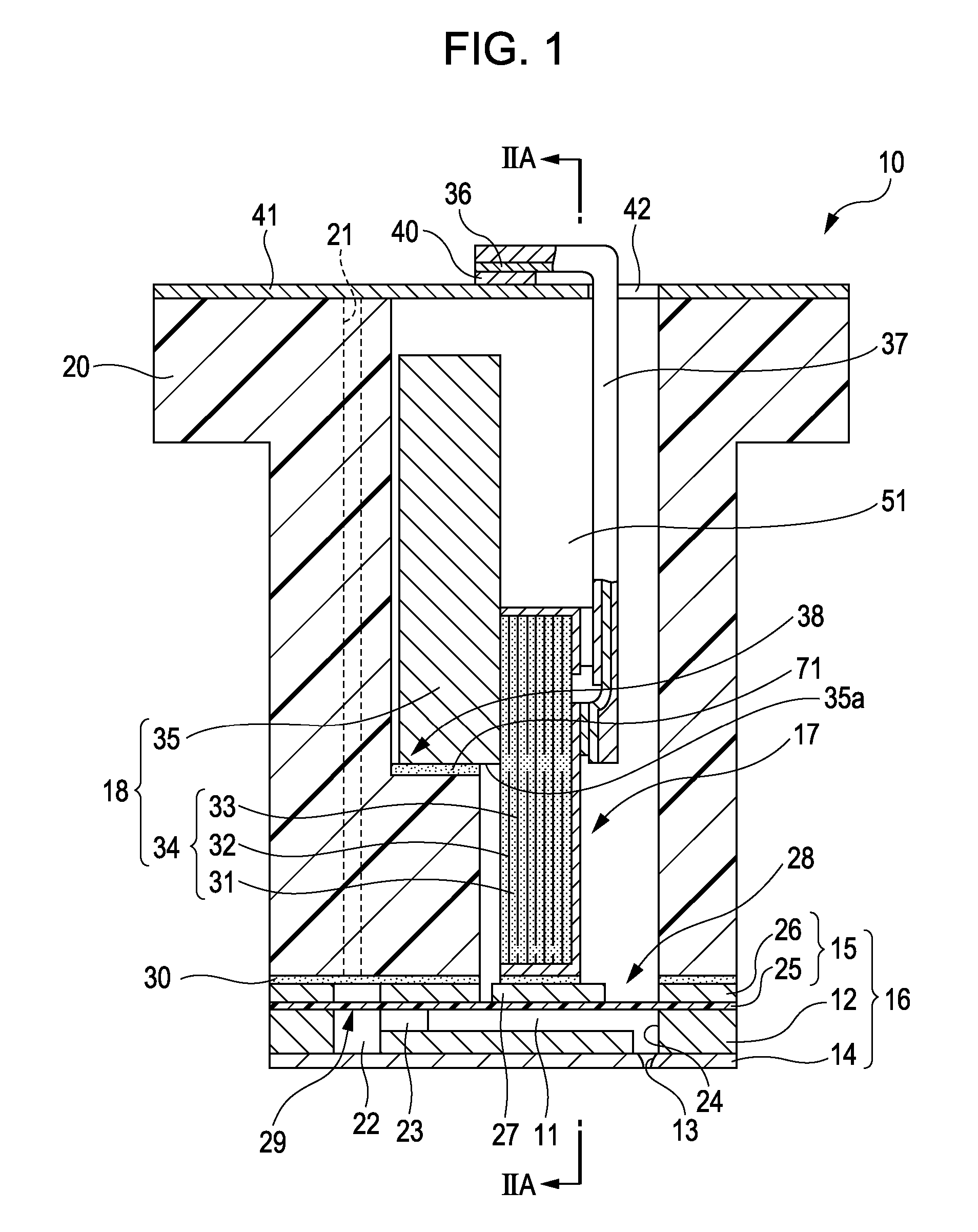
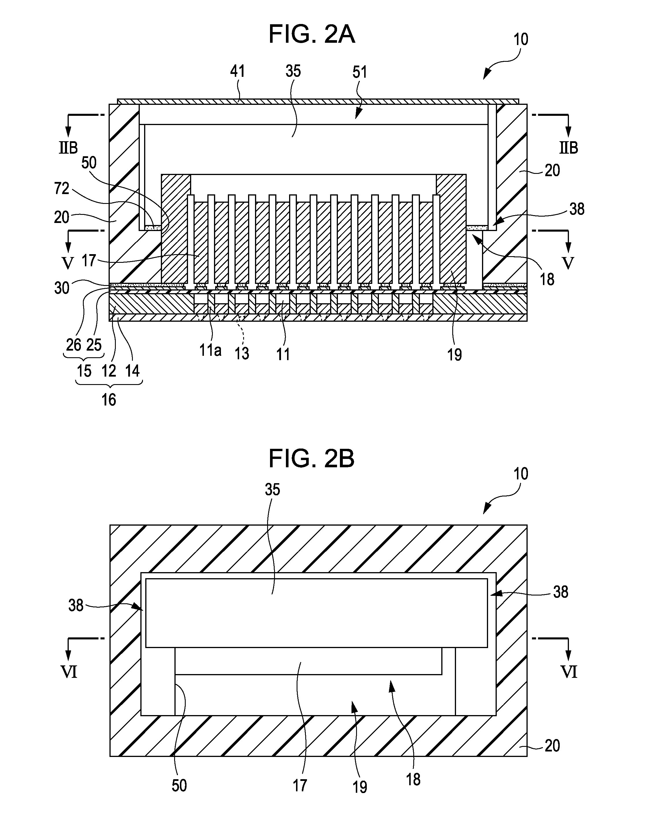
[0025]The invention will be described in detail with reference to an embodiment. FIG. 1 is a sectional view in short direction of a pressure generating chamber of an ink jet recording head as an example of liquid ejection head according to a first embodiment of the invention. FIG. 2A is a sectional view taken along the line IIA-IIA of FIG. 1, and FIG. 2B is a sectional view taken along the line IIB-IIB of FIG. 2A.

[0026]As shown in the figure, an ink jet recording head 10 includes a flow path unit 16 that has a flow path forming substrate 12 having a plurality of pressure generating chambers 11, a nozzle plate 14 in which a plurality of nozzles 13 that communicate with the respective pressure generating chambers 11 are formed by drilling, and a vibration plate 15 disposed on the flow path forming substrate 12 opposite to the nozzle plate 14. The ink jet recording head 10 further includes a piezoelectric element unit 18 that has piezoelectric elements 17 disposed in areas correspondin...


PUM


Abstract

A liquid ejection head includes a flow path unit having pressure generating chambers, a case head that is mounted to the flow path unit, and a piezoelectric element unit having a fixation member and piezoelectric elements, an adhesive surface of the fixation member being adhered to the case head by using a first adhesive and a second adhesive, and the piezoelectric elements being bonded to a piezoelectric element attachment surface of the fixation member which intersects the adhesive surface and also attached to islands that oppose the pressure generating chambers of the flow path unit, wherein the second adhesive has curing time shorter than that of the first adhesive, and the first adhesive has adhesion strength higher than that of the second adhesive and is applied on a first adhesive surface on the adhesive surface of the fixation member which is subject to a reaction force of the piezoelectric elements.

Description

BACKGROUND[0001]1. Technical Field[0002]The present invention relates to liquid ejection heads and liquid ejection apparatuses, and more specifically to ink jet recording heads and ink jet recording apparatuses that eject ink as a liquid.[0003]2. Related Art[0004]Ink jet recording heads that eject ink droplets from nozzles by using pressure, for example, generated by deformation of piezoelectric elements are known as a typical example of liquid ejection head. Specifically, as described in JP-A-2004-74740, an ink jet recording head includes a flow path unit in which pressure generating chambers that communicate with nozzles are formed and having a flow path forming plate and a vibration plate disposed on one face of the flow path forming plate, piezoelectric elements (piezoelectric transducers) secured to the fixation plate corresponding to the respective pressure generating chambers, and a case head (structure) having a housing chamber in which the fixation plate is mounted.[0005]In...

Claims


Application Information

Patent Timeline
Patent Type & Authority Patents(United States)
IPC IPC(8): B41J2/045B41J2/14
CPCB41J2/14201B41J2/14274B41J2002/14362B41J2002/14491
Inventor WATANABE, EIICHIRO
Owner SEIKO EPSON CORP
Why Eureka
Try Eureka