Method of developing a re-entry into a parent wellbore from a lateral wellbore, and bottom hole assembly for milling

a technology of lateral wellbore and parent wellbore, which is applied in the direction of directional drilling, borehole/well accessories, construction, etc., can solve the problems of shearing of the connection with the whipstock, and achieve the effects of increasing the lateral load, amplifying the and creating additional deflection of the mill

Inactive Publication Date: 2009-02-10
WEATHERFORD TECH HLDG LLC
View PDF54 Cites 4 Cited by
  • Summary
  • Abstract
  • Description
  • Claims
  • Application Information

AI Technical Summary

Benefits of technology

[0023]The present invention generally provides a method that allows the operator to re-enter a primary wellbore after a lateral wellbore has been completed. In addition, the present invention provides for a bottom hole assembly that facilitates re-entry into the primary wellbore from a lateral wellbore.
[0027]In addition, a bottom hole assembly that facilitates re-entry into the primary wellbore from a lateral wellbore is provided. The bottom hole assembly generally includes a drill collar, a sub connected to the drill collar, and a lead mill. The lead mill has a body connected to the sub, and blades. The blades are dimensioned to increase lateral contact pressure between the blades and the surrounding tubular.
[0029]In one arrangement, the bottom hole assembly includes an angled tool joint to create additional deflection of the mill against the liner. The angled tool joint may be a bent sub, a bent extension sub, or a bent upper mill. Alternatively, the lead mill may have a cutting structure that is eccentrically arranged. The eccentric arrangement will increase the lateral load on the surrounding liner by amplifying the deflection of the mill against the liner during rotation.

Problems solved by technology

Rotation of the string rotates the mill, and causes shearing of the connection with the whipstock.

Method used


Image

  • Method of developing a re-entry into a parent wellbore from a lateral wellbore, and bottom hole assembly for milling
  • Method of developing a re-entry into a parent wellbore from a lateral wellbore, and bottom hole assembly for milling
  • Method of developing a re-entry into a parent wellbore from a lateral wellbore, and bottom hole assembly for milling

Examples


Embodiment Construction

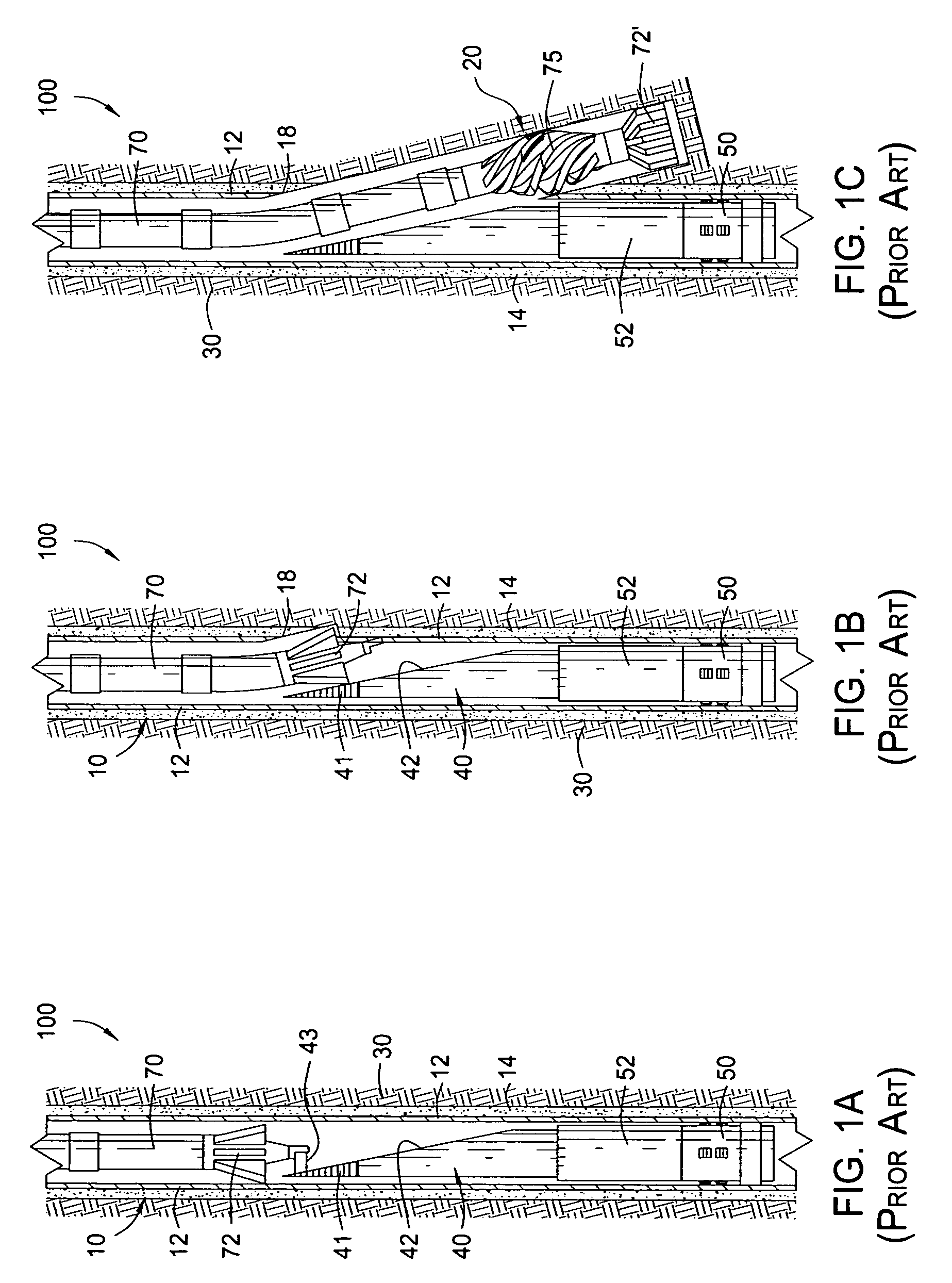
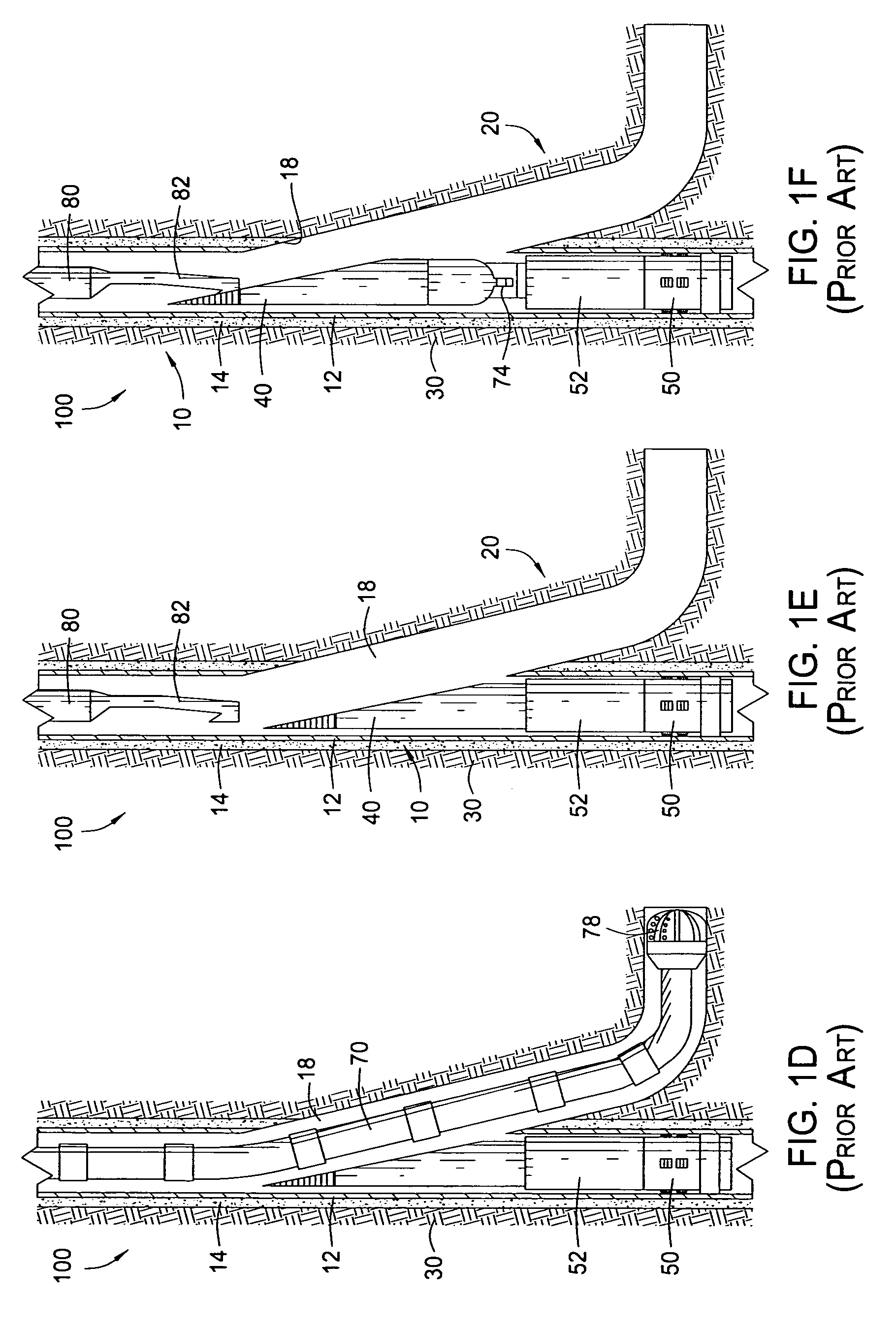
[0048]FIG. 2A is a cross-sectional view of a wellbore 100. The wellbore 100 has both a primary wellbore 10, and a lateral wellbore 20 having been drilled off of the primary wellbore 10. A liner 28 is visible, providing access to the lateral wellbore 20 through a window 18. The liner 28 includes a curved portion 45, or “curvature,” that substantially blocks passage through the primary wellbore 10 at the point of intersection with the lateral wellbore 20.

[0049]In FIG. 2A, a bottom hole assembly 200 is being moved into the primary wellbore 10. The bottom hole assembly 200 is not completely visible, but is just beginning to enter the liner 28. It is understood, of course, that the features of FIG. 2A are not to scale, and that the liner 28 may extend from 100 to 500 feet, depending upon desired build-rate.

[0050]FIG. 3 provides a perspective view of a bottom hole assembly 200 for forming an entry path through a tubular body, in one embodiment. In this arrangement, the bottom hole assembl...


PUM


Abstract

A method is provided that allows the operator to re-enter a primary wellbore from a lateral wellbore after the lateral wellbore has been completed. The method generally comprises the steps of locating a cutting device such as a milling bit adjacent a tubular such as a liner within a wellbore, rotating the milling bit while maintaining an axial position of the milling bit relative to the liner to initiate an opening, and rotating and axially advancing the milling bit to complete the opening. In addition, a bottom hole assembly that facilitates re-entry into the primary wellbore from a lateral wellbore is provided. The bottom hole assembly generally includes a drill collar or other heavy pipe structure, and a mill. The mill has a body and cutting structures. The cutting structures apply lateral force against a surrounding pipe to form an initial lip through the wall of the pipe.

Description

BACKGROUND OF THE INVENTION[0001]1. Field of the Invention[0002]Embodiments of the present invention generally relate to the practice of sidetrack drilling for hydrocarbons. More specifically, this invention pertains to a method of developing a re-entry into a parent wellbore from a lateral wellbore. The present invention also relates to a bottom hole assembly for providing re-entry into a parent wellbore.[0003]2. Description of the Related Art[0004]In recent years, technology has been developed which allows an operator to drill a primary vertical well, and then drill an angled lateral borehole off of the primary well at a chosen depth. Generally, the primary vertical wellbore is first cased with a string of casing and cemented. Then a tool known as a whipstock is positioned in the casing at the depth where deflection is desired. The whipstock is specially configured to divert milling bits and then a drill bit in a desired direction for forming a lateral borehole. This process is so...

Claims


Application Information

Patent Timeline
Patent Type & Authority Patents(United States)
IPC IPC(8): E21B29/06E21BE21B7/06E21B29/00E21B41/00
CPCE21B29/06E21B41/0035E21B7/06
Inventor CARTER, JR., THURMAN B.ROBERTSON, ROBERT E.HALFORD, HUBERT E.REDLINGER, THOMAS M.
Owner WEATHERFORD TECH HLDG LLC
Why Eureka
Try Eureka