Vision enhancing device

a technology of enhancing device and enhancing lens, which is applied in the direction of prosthesis, instruments, lenses, etc., can solve the problems of inability to read, drive, drive, and watch television,

Inactive Publication Date: 2009-02-10
STC UNM
View PDF6 Cites 9 Cited by
  • Summary
  • Abstract
  • Description
  • Claims
  • Application Information

AI Technical Summary

Problems solved by technology

In macular degeneration, the light-sensitive cells are damaged and, thus, inoperative.
In the advanced stages of macular degeneration, central vision may be reduced or completely lost making it impossible to read, watch television, drive, sew, etc.
However, the bioptic telescopes can only achieve a moderate image enlargement to a limited visual field and are cumbersome.
However, distortion of the image increases with the power of magnification and the eyeglasses can be heavy due to the thickness of the lens.

Method used


Image

  • Vision enhancing device
  • Vision enhancing device
  • Vision enhancing device

Examples


example 1

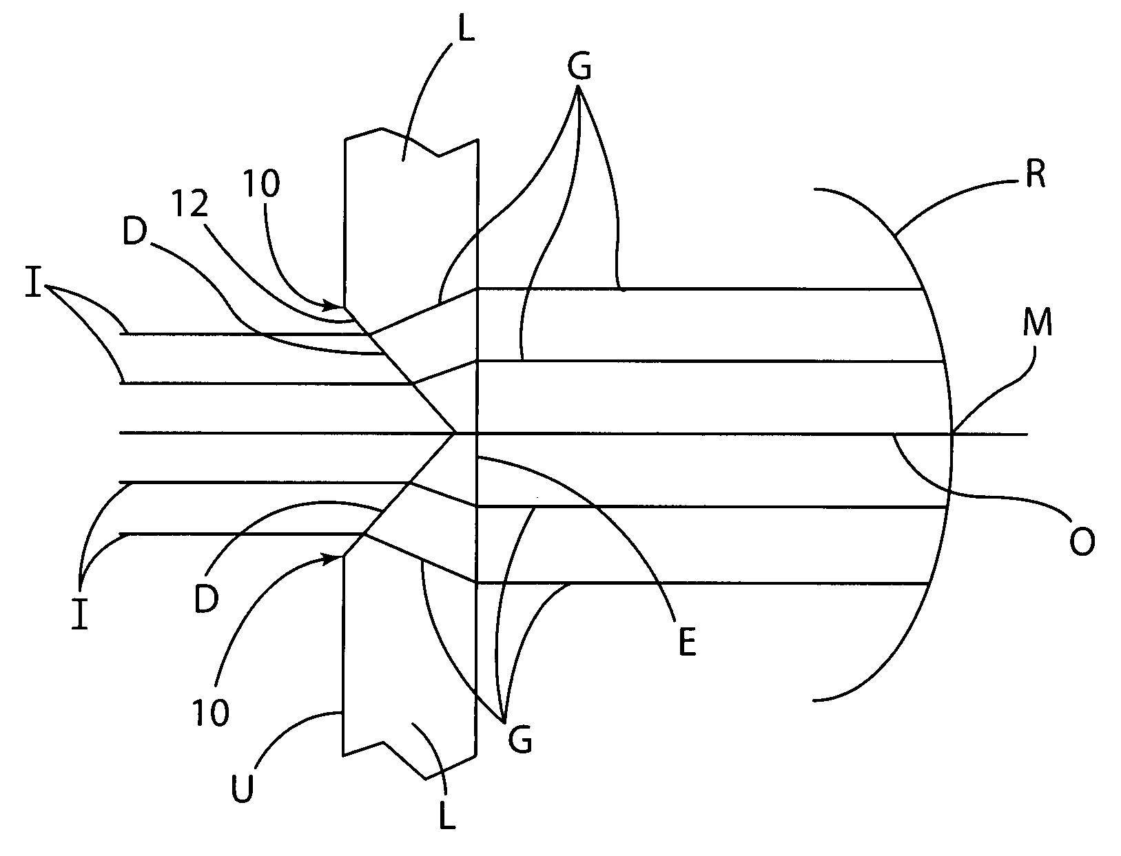
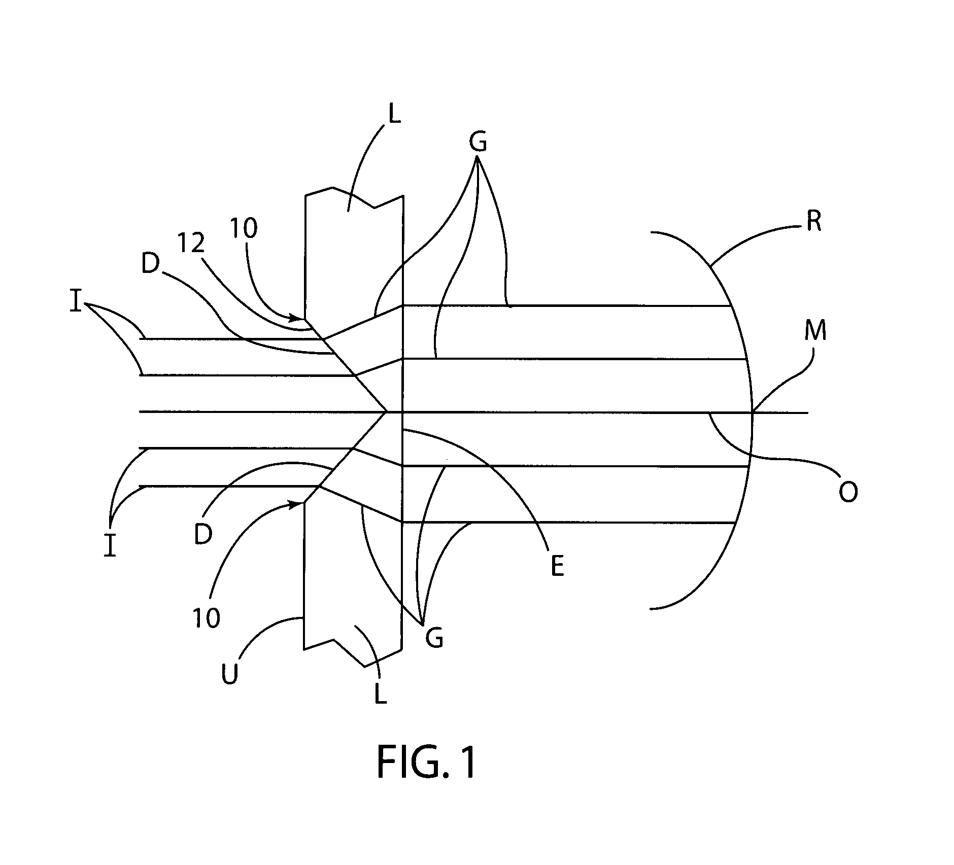
[0045]The design of this example is a conical surface drilled into a lens, as described above and shown in FIG. 1. The angle of incidence, B, see FIG. 6, means that the conical half angle A=90°−B. If the emergent angle from the lens is c, determined for a contact lens to be about 4.7°, and if the emergent ray is to strike the retina just outside the macula, then the interior angle, called b2, is determined by applying Snell's Law: sin b2=sin c / n. The interior ray will reach the conical surface at an angle b1=B−b2, where B is the apex angle of the wedge formed by the conical half angle A and the emergent surface. As the use of the same symbol indicates, B is equal to the angle of incidence to the lens surface. Snell's Law must be applied to the ray emergent inside the light diverging surface so that the angle of incidence is B; ie., sin B=n sin (B−b2), with b2=sin−1(sin c / n). the angle c and the index of refraction selected then determine B and hence A=90°−B. If the angles are relati...

example 2

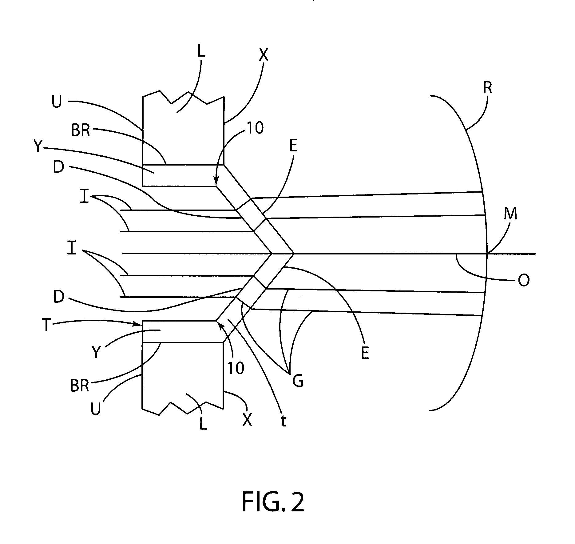
[0047]Referring to FIG. 2, the entry and emergent surfaces are seen to be parallel (or coaxial with the same conical angle, to be precise). In this case, the incident and emergent rays will be parallel, with the emergent ray displaced away from the incident as shown. Snell's Law provides the amount of displacement for a given conical angle A. Again the incident angle for Snell's Law is B, see FIG. 6, where A=90°−B. The parameter of interest is the displacement, since this is the way the light is directed outside the macula. The displacement depends on the angle of incidence, the index of refraction, and the thickness t of the lens having the light diverging surface D thereon. Using Snell's Law, one finds sinb1=sinB / n. To calculate the displacement, one obtains the length of the ray's path in the glass, L=tcos b1, where t is the thickness (to be determined). Then the displacement is d=t cos b1 sin (B−b1). If one takes n=1.5, and the displacement, d, is required to be 2 mm, and B is s...


PUM


Abstract

A vision enhancing device for a person having macular degeneration of the retina, comprises a lens and a light diverging surface on the lens that symmetrically diverges away from the eye at an angle relative to an optic axis to redirect incident light away from the optic axis outwardly toward an un-diseased region of the retina. The light diverging surface can be a smooth surface, which can be a continuous curved surface, and can be a diverging conical surface. The lens can be an eyeglass lens, contact lens, intraocular lens, telescopic lens, correction lens, or magnification lens. A light diverging insert having a conical surface and, optionally, an end surface can be used in a lens for redirecting light to the un-diseased region of the retina.

Description

RELATED APPLICATIONS[0001]This application claims benefits and priority of provisional application Ser. No. 60 / 654,999 filed Feb. 22, 2005.FIELD OF THE INVENTION[0002]The invention relates to a vision enhancing device for a person with macular degeneration, and in particular, a vision enhancing device having a light diverging surface on a lens that diverges light way from the optic axis outwardly toward the un-diseased region of the retina.BACKGROUND OF THE INVENTION[0003]The retina of the eye has two parts: the macula and peripheral retina. The macula is very small and in the center of the retina. The area surrounding the macula is the peripheral retina and makes up 95% of the retina.[0004]The macula is necessary for normal central vision acuity and consists mostly of light-sensitive cells called cones. In macular degeneration, the light-sensitive cells are damaged and, thus, inoperative. Common causes of macular degeneration are age, diabetic retinopathy, ocular vascular accidents...

Claims


Application Information

Patent Timeline
Patent Type & Authority Patents(United States)
IPC IPC(8): G02C7/00A61F2/16G02C7/02G02B25/00
CPCG02C7/02G02C7/14
Inventor HULL, MCALLISTER H.
Owner STC UNM
Why Eureka
Try Eureka