Key guide structure in keyboard apparatus

a technology of guiding structure and keys, applied in the direction of instruments, stringed musical instruments, measurement devices, etc., can solve the problems of dimensional stability, positional accuracy and appearance, noise sound produced, and keys cannot be molded accurately into original-designed dimensions, so as to prevent the production of unwanted noise sound, maintain design accuracy, and minimize the variation of gaps between adjoining keys

Active Publication Date: 2009-02-10
YAMAHA CORP
View PDF7 Cites 7 Cited by
  • Summary
  • Abstract
  • Description
  • Claims
  • Application Information

AI Technical Summary

Benefits of technology

[0008]In view of the foregoing, it is an object of the present invention to provide a key guide structure in a keyboard apparatus which can maintain design accuracy without being influenced by change and variation of resin molding conditions and aftercontraction of the resin mold. It is another object of the present invention to provide a key guide structure which can prevent vertical movement of a key from becoming unsmooth and prevent production of unwanted noise sound due to inappropriate contact. It is still another object of the present invention to provide a key guide structure which can minimize variation in gaps between adjoining keys by maintaining positional accuracy, in a horizontal key-arranged direction, of the keys and enhance the outer appearance of the keys etc.
[0009]In order to accomplish the above-mentioned objects, the present invention provides an improved key guide structure in a keyboard apparatus having a frame and a key pivotably mounted on the frame, which comprises: a key-side guide member provided inside the key and having at least one convexly-formed portion projecting from an inner surface of a distal end portion of the key, remote from a pivot point of the key, toward the pivot point; and a frame-side guide member provided on the frame in such a manner that the frame-side guide member permits movement of the key-side guide member along a pivoting direction of the key but limits lateral movement of the key-side guide member.
[0010]Because the key-side guide member has at least one convexly-formed portion projecting from the inner surface of the distal end portion of the key, remote from the pivot point of the key, toward the pivot point and the frame-side guide member is provided so as to permit the movement of the key-side guide member along the pivoting direction of the key but limit the lateral movement of the key-side guide member, the present invention can provide a key guide structure that can maintain the design accuracy without being influenced by change and variation of resin molding conditions and aftercontraction of the resin mold. Further, the present invention can avoid production of unwanted mechanical noise sound. Further, the present invention can also maintain the positional accuracy, in the key-arranged direction, of the key and thus, it can minimize variation in gaps between adjoining keys and thereby enhance the outer appearance of the keys etc.
[0011]As an example, the frame-side guide member has two members defining a guide channel to allow one the convexly-formed portion of the key-side guide member to enter the guide channel, and wherein, by the guide channel, the frame-side guide member not only guides movement, along the pivoting direction of the key, of the key-side guide member but also limits lateral movement of the key-side guide member. With such arrangements, the key-side guide member has to have only one convexly-formed portion, so that molding of the key can be facilitated. Further, the guide channel defined by the two members of the frame-side guide member is open at least at its portion adjacent to the distal end of the key frame (i.e., the two members are spaced from each other in the key-arranged direction at least at their portions adjacent to the distal end of the key frame), to permit entry of the key-side guide member. Thus, in a case where a lubricant agent (such as grease) has to be put between the guide-side guide member and the frame-side guide member, and when the lubricant agent is to be applied to sliding contact portions of the frame-side guide member, it is only necessary to apply the lubricant agent, just once per key, through the open portion of the frame-side guide member; thus, the operation for applying the lubricant agent can be performed with ease even if it is manual. Further, if the lubricant agent application operation is automatized, the operation can be performed in an even more simplified manner and with a minimized number of steps.
[0012]As an example, the two members of the frame-side guide member define two side surfaces of the guide channel with no member provided for interconnecting the two members to define a bottom of the guide channel. With this arrangement, the operation for applying the lubricant agent into the guide channel, defined by the two members of the frame-side guide member, can be performed with an increased ease. Thus, this arrangement is more suitable for automatization of the lubricant agent application operation
[0013]As an example, the frame-side guide member comprises a guide rail formed by means of a single member, and the key-side guide member is disposed so as to sandwich the guide rail by two the convexly-formed portions so that the guide rail not only guides movement, along the pivoting direction of the key, of the key-side guide member but also limits lateral movement of the key-side guide member. Because the frame-side guide member can be constructed of only one member, molding of the key frame can be facilitated.

Problems solved by technology

Thus, the disclosed key guide structures would present various problems pertaining to dimensional stability, positional accuracy and appearance of the keys, etc.
Thus, keys can not be molded accurately into originally-designed dimensions.
Thus, unintended contact would occur between the key and the corresponding key guide, with the result that there would arise problems with the key guide function, such as unsmooth vertical movement of the key, noise sound produced due to the unsmooth contact between the key and the key guide, etc.
Thus, the closer to the pivot point of the key (i.e., the farther from the distal end) the position of the key guide (key guide section), the more difficult would it become to achieve positional accuracy, in the key-arranged direction, of the key's distal end portion, which would result in great differences in gaps between adjoining keys.
However, unwanted sinkage or sink tends to occur in the outer surface of a portion where the rib Ra or Rb is provided.
Further, the greater the distance between the side surface of the key (i.e., width of the key), or the greater the height of the rib, the more easily such sink tend to occur.
Therefore, the key position problem can be avoided more easily if the position Pa of the key guide section of FIG. 9 is closer to the distal end (front end surface) of the key; in such a case, however, the outer surface of the portion where the deformation-preventing rib Ra is provided may sink more easily than where the key guide section is at the position Pb, and thus, the appearance of the outer surface would be aesthetically impaired.

Method used


Image

  • Key guide structure in keyboard apparatus
  • Key guide structure in keyboard apparatus
  • Key guide structure in keyboard apparatus

Examples


Embodiment Construction

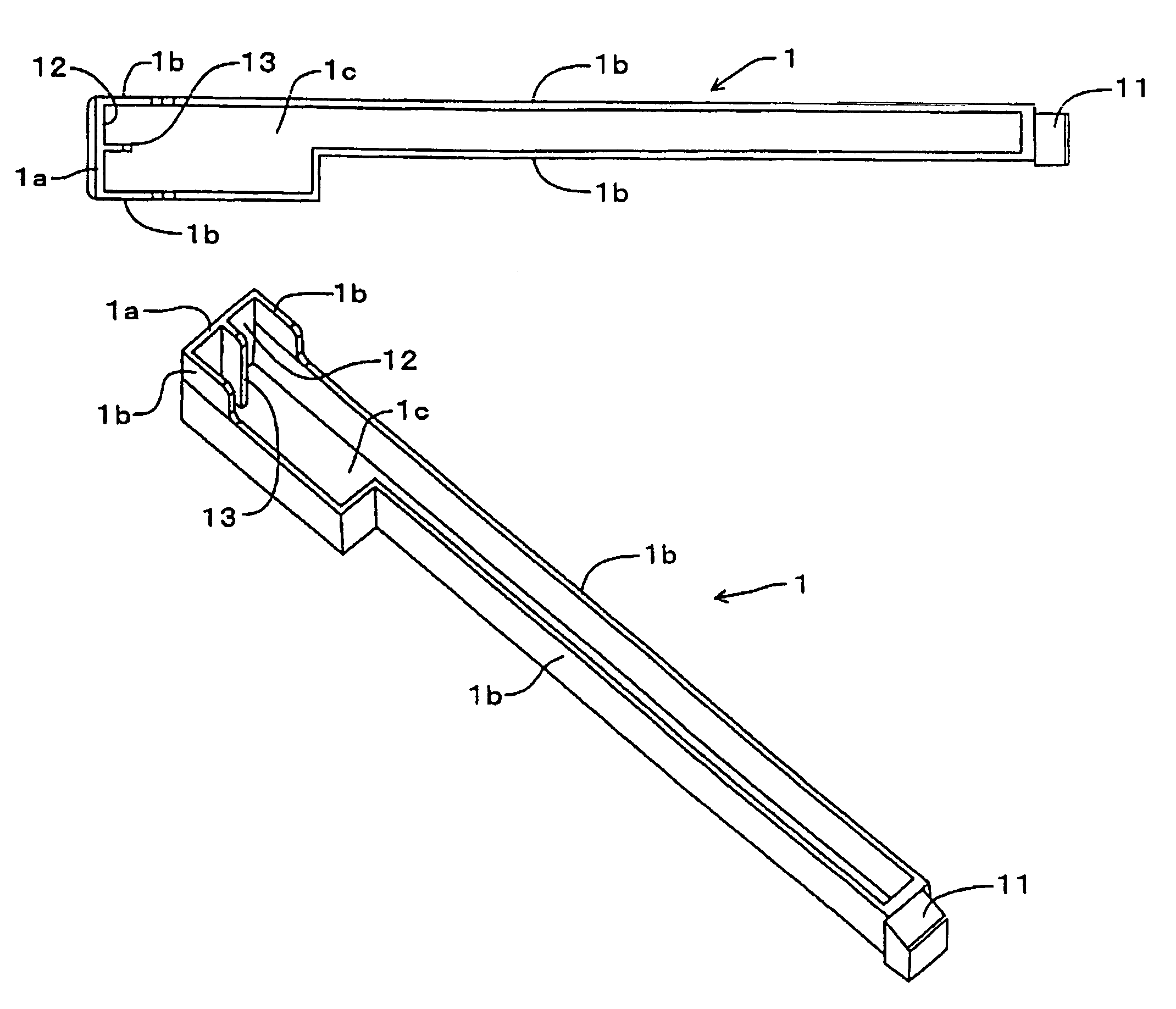
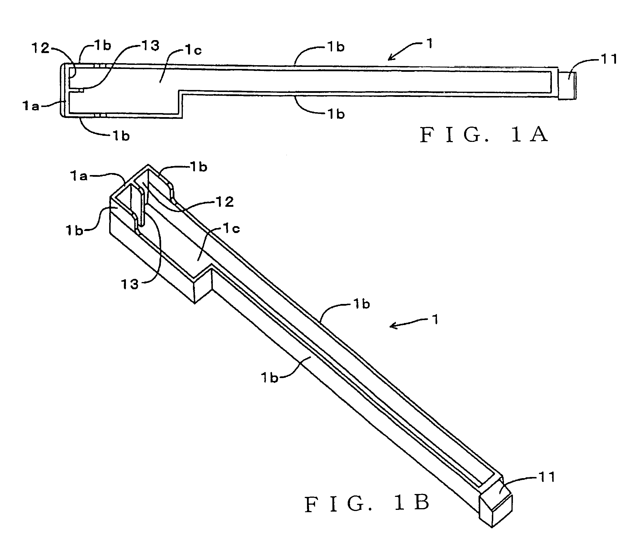
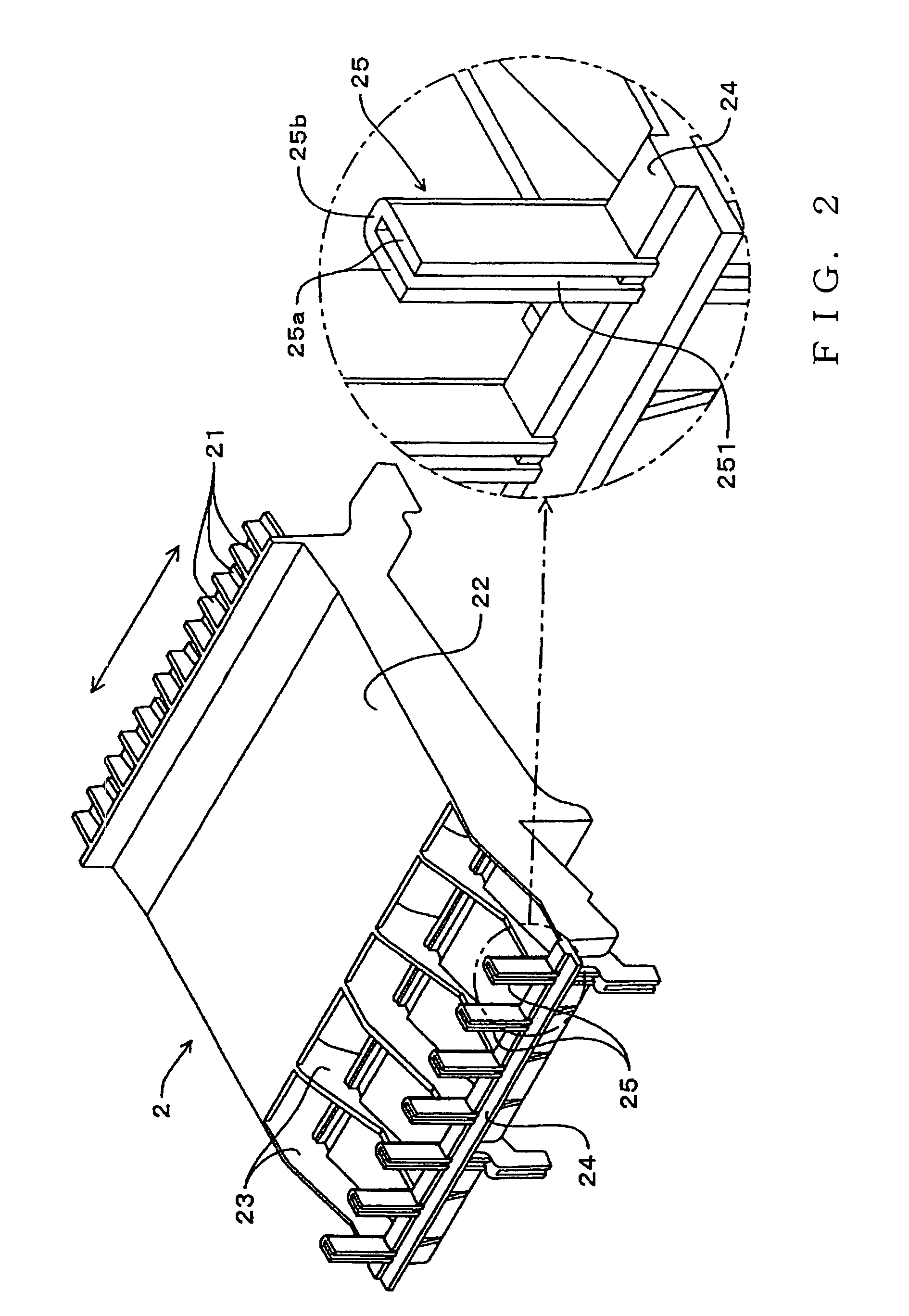
[0025]FIG. 1A is a bottom view of a white key in a keyboard apparatus to which is applied a key guide structure in accordance with an embodiment of the present invention, arid FIG. 1B is a bottom perspective view of the key. FIG. 2 is a top perspective view showing principal sections of a key frame in the keyboard apparatus. FIG. 3A is a side sectional view showing a key in a released position, and FIG. 3B is a side sectional view showing a key in a depressed position. In FIGS. 3A and 3B, a left side is where a human player is located at the time of a performance (hereinafter “player side”), and a direction perpendicular to the sheet of FIG. 3 is a direction in which a plurality of keys are arranged. Throughout this specification, “upper”, “lower”, “left” and “right” represent directions as viewed from the player side, and “front” represents a direction toward the player side while “rear” represents a direction away from the player side, i.e. toward the back of the keyboard apparatu...


PUM


Abstract

Keyboard apparatus has a frame and a key pivotably mounted on the frame. Key guide structure includes a key-side guide member provided inside the key, and a frame-side guide member provided on the frame. The key-side guide member has at least one convexly-formed portion projecting from the inner surface of a distal end portion of the key, remote from a pivot point of the key, toward the pivot point. The frame-side guide member permits movement of the key-side guide member along a pivoting direction of the key, but limits lateral movement of the key-side guide member.

Description

BACKGROUND OF THE INVENTION[0001]The present invention relates to a key guide structure for use in a keyboard apparatus, having keys pivotably mounted on a key frame, which guides pivoting movement of a key by means of a key-side guide member provided on an inner wall surface of the key and a frame-side guide member provided integrally with the key frame.[0002]Key guide structures of the aforementioned type are disclosed, for example, in Japanese Patent Laid-open Publication No. HEI-9-244656 (patent literature 1) (corresponding to U.S. Pat. No. 5,824,928) and Japanese Patent Publication No. 3044810 (patent literature 2). In the key guide structure disclosed in patent literature 1, a key guide is disposed on an upper portion of a front plate of a frame and inside a distal end portion of a white key, and movement of the white key is guided by cooperation between the key guide and two side surfaces (side walls) of the while key which are opposed to each other in a direction in which a ...

Claims


Application Information

Patent Timeline
Patent Type & Authority Patents(United States)
IPC IPC(8): G01D13/02
CPCG10C3/12
Inventor WATANABE, KEISUKE
Owner YAMAHA CORP
Why Eureka
Try Eureka