Superconducting rotating machines with stationary field coils

a superconducting coil and rotating machine technology, applied in the direction of windings, magnetic circuit rotating parts, magnetic circuit shapes/forms/construction, etc., can solve the problems of increasing the complexity of the overall system design, adding the superconducting field coil to substantial thermal stresses, centrifugal stresses, etc., to achieve the effect of increasing the torque density, improving reliability, and improving performance characteristics

Active Publication Date: 2009-02-10
GENERAL ELECTRIC CO
View PDF33 Cites 43 Cited by
  • Summary
  • Abstract
  • Description
  • Claims
  • Application Information

AI Technical Summary

Problems solved by technology

This transfer of cryogenic fluid from a stationary cryocooler to a rotating cooling loop adds considerable complexity to the overall system design.
In addition, installation of a superconducting field coil on the rotor subjects the superconducting field coil to substantial thermal stresses, centrifugal stresses, and electrical design challenges.
One such electrical design challenge is providing an electrical connection through the rotor to power the superconducting field coil.
Accordingly, designing, fabricating and operating such a rotor may be difficult.
Specifically, because the coils are coupled to the rotor, the coils may be subjected to centrifugal forces that may cause strains and degrade the performance of the superconductor.
However, the relatively small usable airgap is a design challenge presented by the radial flux HIA design.
The axial-flux stationary superconducting field coil structure employs a split stator, which adds to the complexity of the machine.

Method used


Image

  • Superconducting rotating machines with stationary field coils
  • Superconducting rotating machines with stationary field coils
  • Superconducting rotating machines with stationary field coils

Examples


Embodiment Construction

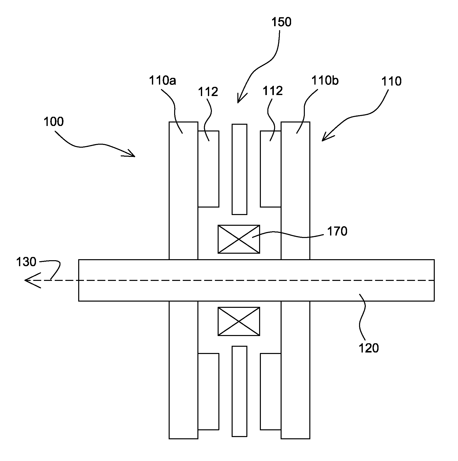
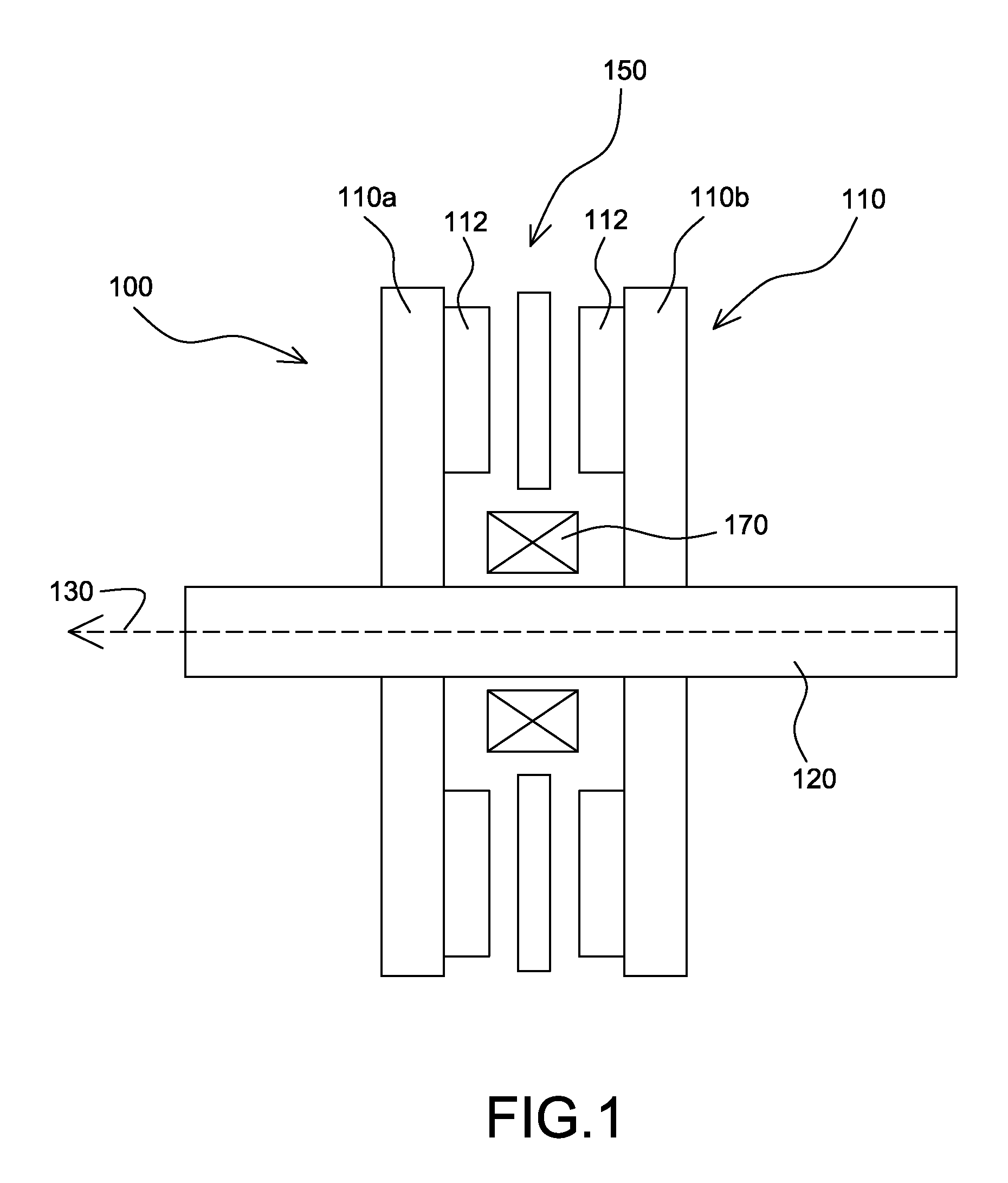
[0021]FIG. 1 is a cross-sectional view of an exemplary embodiment of an electrical machine 100. The machine 100 may operate as a motor and / or as a generator as desired. As shown, the machine 100 includes a shaft 120 adapted to rotate about a longitudinal axis 130 of the shaft. For the exemplary embodiment shown in FIG. 1, the shaft 120 is formed of a magnetic material. For particular embodiments, the magnetic material employed in the shaft 120 is characterized by a high saturation magnetization, for example above 1.7 Tesla, more particularly above 1.8 Tesla and still more particularly about 2.3 Tesla. Example magnetic materials for the shaft include, but are not limited to, iron-cobalt alloys. As used herein, iron-cobalt alloys may include other constituents, for example to strengthen the alloy. The invention is not limited to a specific shaft construction, and non-limiting examples of the shaft include monolithic constructions and dual or multi-alloy constructions. As discussed bel...


PUM


Abstract

A machine includes a shaft adapted to rotate about a longitudinal axis and formed of a magnetic material and a rotor assembly rotationally engaged with the shaft The rotor assembly includes a pair of rotor disks comprising a magnetic material, each of the rotor disks having a number of magnetic poles, the magnetic poles being spaced apart circumferentially. The rotor disks are coupled to the shaft for rotation about the shaft and generation of a rotating permeance wave. The machine further includes a stator assembly that includes a magnetic core stator disposed between the rotor disks, a number of armature windings supported on the magnetic core stator, and a stationary superconducting field coil disposed between the magnetic core stator and the shaft. The stationary superconducting field coil is configured as a stationary magneto-motive force (MMF) source for the rotating permeance wave produced by the rotor assembly to produce a rotating magnetic field.

Description

STATEMENT REGARDING FEDERALLY SPONSORED RESEARCH & DEVELOPMENT[0001]This invention was made with Government support under contract number FA8650-04-G-2466-001 awarded by the United States Air Force (USAF). The Government has certain rights in the invention.BACKGROUND OF THE INVENTION[0002]The present invention relates generally to electrical motor / generators, and more particularly to machines including superconducting windings.[0003]Typically, designs for superconducting electric machines include a superconducting field coil installed on the rotor. The superconducting coil is maintained at a temperature below its critical temperature using a continuous supply of cryogenic fluid, such as liquid helium (He) for conventional superconductors and liquid nitrogen (N2) or neon (Ne) for high temperature superconductors (HTS). In order to cool the field coil, the cryogenic fluid is typically supplied to the superconducting field coil from a stationary cryocooler through a transfer coupling t...

Claims


Application Information

Patent Timeline
Patent Type & Authority Patents(United States)
IPC IPC(8): H02K31/00
CPCH02K19/103H02K19/20H02K55/02Y02E40/622Y02E40/60
Inventor QU, RONGHAIBRAY, JAMES WILLIAM
Owner GENERAL ELECTRIC CO
Why Eureka
Try Eureka