Elevator traffic control

a technology for elevators and passengers, applied in the direction of computer control, elevators, instruments, etc., can solve the problems of reducing not always giving the best individualized service to passengers, etc., and achieve the effect of maximizing the handling capacity of the elevator system

Active Publication Date: 2009-02-17
OTIS ELEVATOR CO
View PDF7 Cites 17 Cited by
  • Summary
  • Abstract
  • Description
  • Claims
  • Application Information

AI Technical Summary

Problems solved by technology

While channeling systems are good for mass efficiency, they do not always give the best individualized service to a passenger.
On the other hand, destination entry systems are good for individual service but often reduce the handling capacity of the elevator system.

Method used


Image

  • Elevator traffic control
  • Elevator traffic control
  • Elevator traffic control

Examples


Embodiment Construction

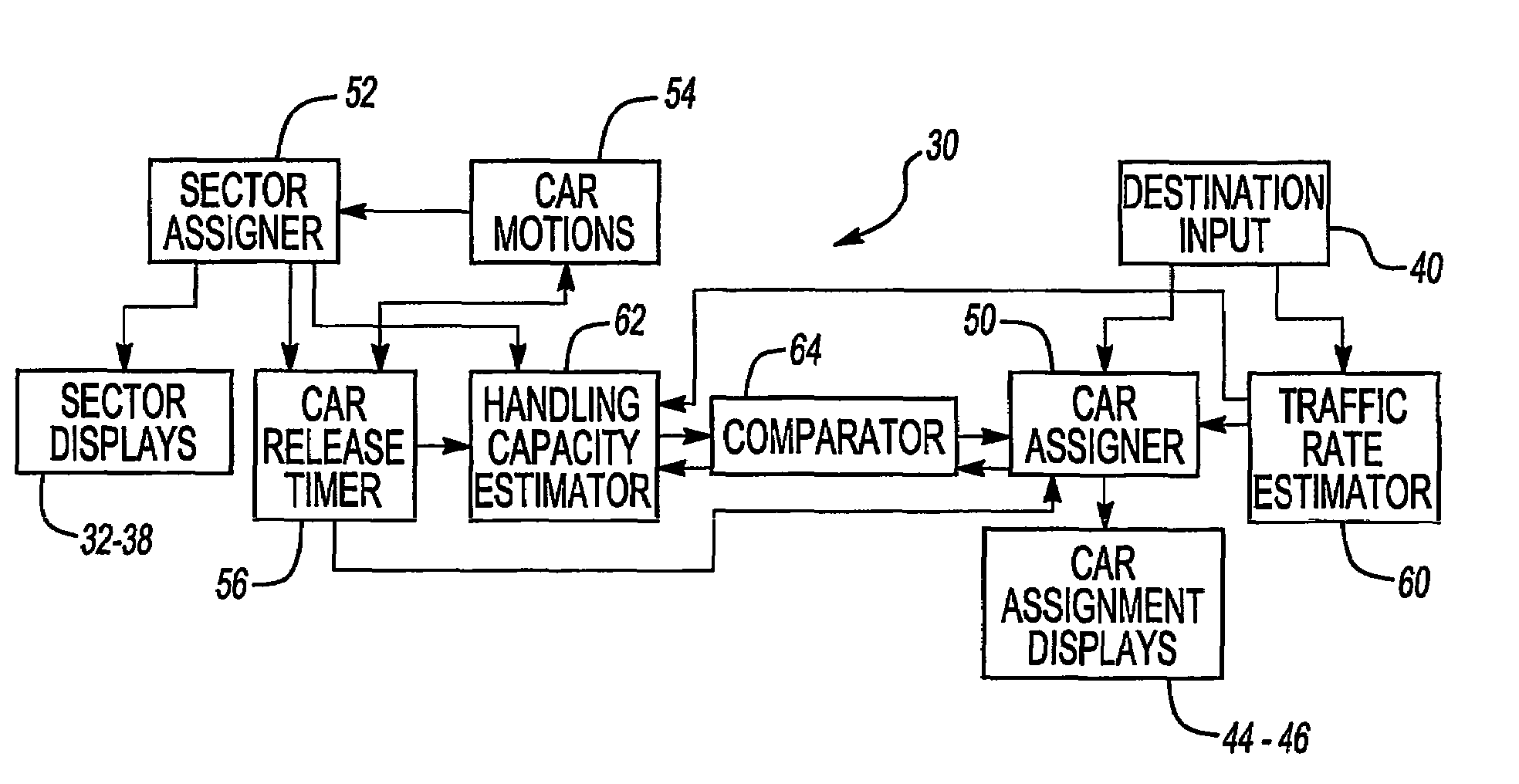
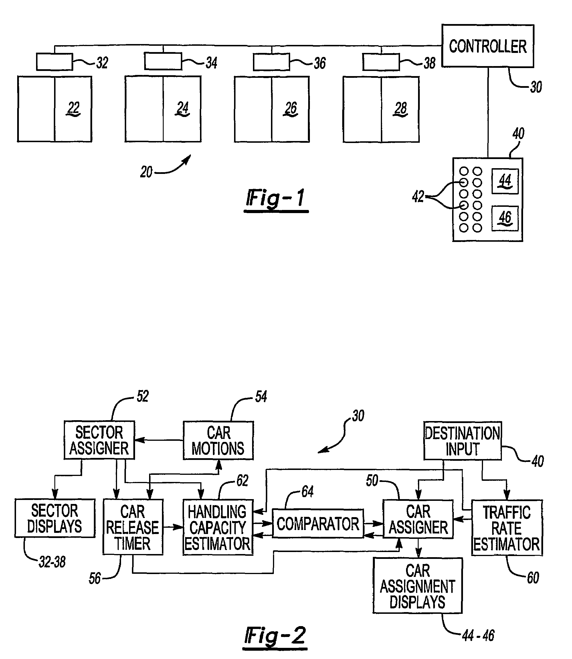
[0015]FIG. 1 schematically shows an elevator system 20 having a plurality of elevator cars 22, 24, 26 and 28. A controller 30 controls the movement of the cars in a manner to maximize the handling capacity of the elevator system. The controller 30 preferably uses known channeling techniques whereby the individual cars are assigned to specific sectors that include selected floors to which the cars are able to travel. The controller 30 controls displays 32, 34, 36 and 38, respectively, to provide an indication to passengers which floors each of the cars may reach. In one example, the displays are associated with each car at a lobby level to facilitate passengers boarding the appropriate car.

[0016]The illustrated example of FIG. 1 includes a primary destination entry device 40 that preferably is positioned in an appropriate portion of a building lobby or a main elevator system entry level. The primary destination entry device 40 includes a plurality of inputs 42 that allow passengers t...


PUM


Abstract

An elevator traffic flow control strategy utilizes the advantages of sector assignment channeling and destination entry systems. A controller (30) monitors a handling capacity (62) of the system to determine when it is advisable to override the sector assignments (52) to provide improved passenger service.

Description

FIELD OF THE INVENTION[0001]This invention generally relates to directing elevator cars and passengers to specific elevator cars to maximize the efficiency of the elevator system.DESCRIPTION OF THE RELATED ART[0002]Elevator systems often include a plurality of cars that move between levels within a building for carrying passengers or cargo as needed. Depending on the size of the building, elevator systems can service a large traffic volume of passengers to a relatively high number of floors. In order to maximize the efficiency of the elevator system, different approaches are known for controlling the movement of the elevator cars.[0003]One approach is known as channeling or sectoring where elevator cars are assigned to specific groups of floors (i.e., sectors) within a building so that each car returns to a lobby floor to accept new passengers in a manner that increases the traffic volume that the elevator system can handle. A variety of features and variations within channeling sys...

Claims


Application Information

Patent Timeline
Patent Type & Authority Patents(United States)
IPC IPC(8): B66B1/16
CPCB66B1/2458B66B3/00B66B3/006B66B2201/103B66B2201/211B66B2201/215B66B2201/302
Inventor SIRAG, JR., DAVID J.
Owner OTIS ELEVATOR CO
Why Eureka
Try Eureka