Method and system of dynamic traffic control in a communication network

Inactive Publication Date: 2002-12-24
SIEMENS AG
View PDF5 Cites 59 Cited by
  • Summary
  • Abstract
  • Description
  • Claims
  • Application Information

AI Technical Summary

Benefits of technology

An object of the present invention is to avoid the above-identified disadvantages in the prior art. Another object of the present invent

Problems solved by technology

As a result thereof, the routing can only react very unsatisfactorily to unplanned, extraordinary load situations.
What is thereby disadvantageous, among other things, is the great outlay for network-central processors, data transmission and additionally required calculating capacity in the network nodes.
These methods have the disadvantage that the non-standardized interf

Method used


Image

  • Method and system of dynamic traffic control in a communication network
  • Method and system of dynamic traffic control in a communication network

Examples


Embodiment Construction

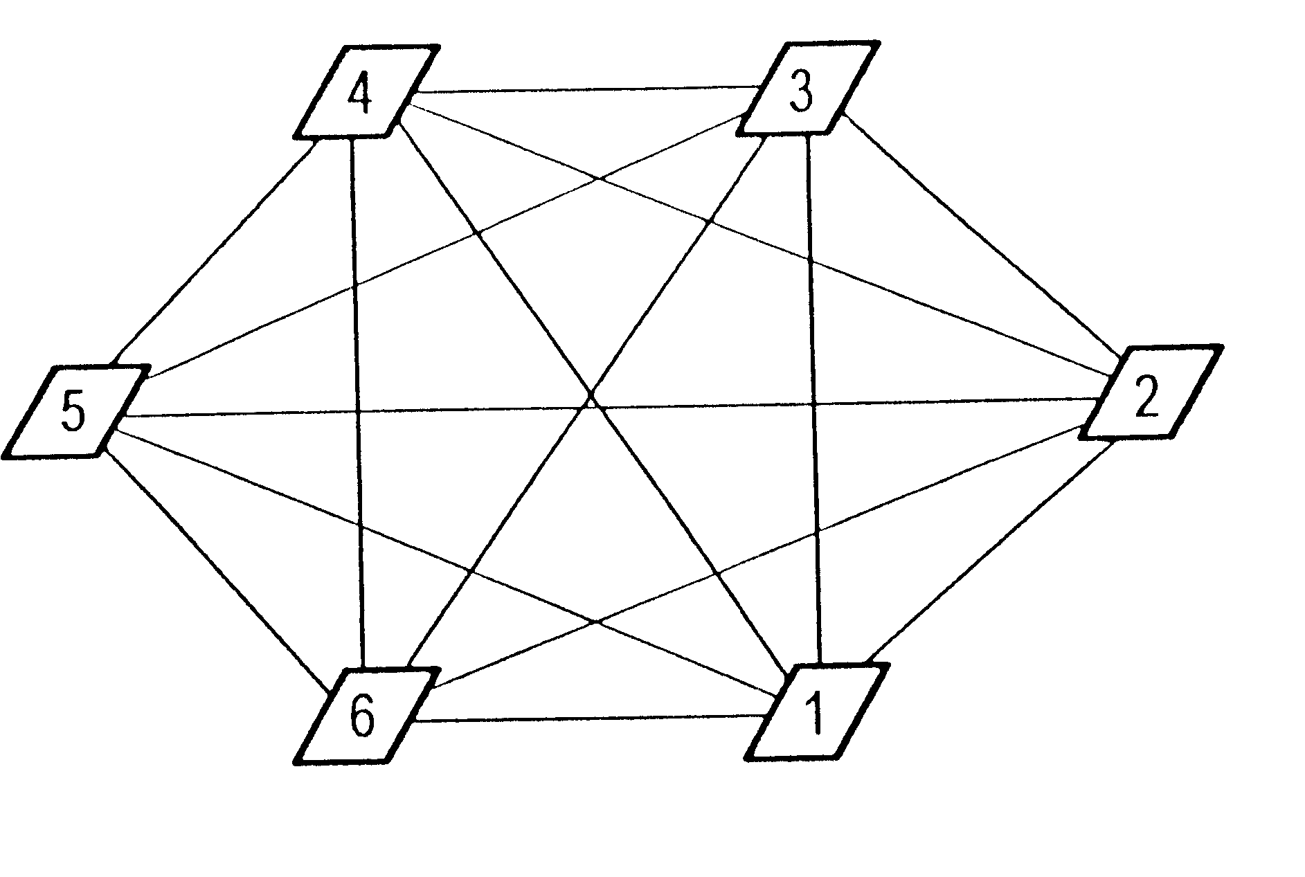
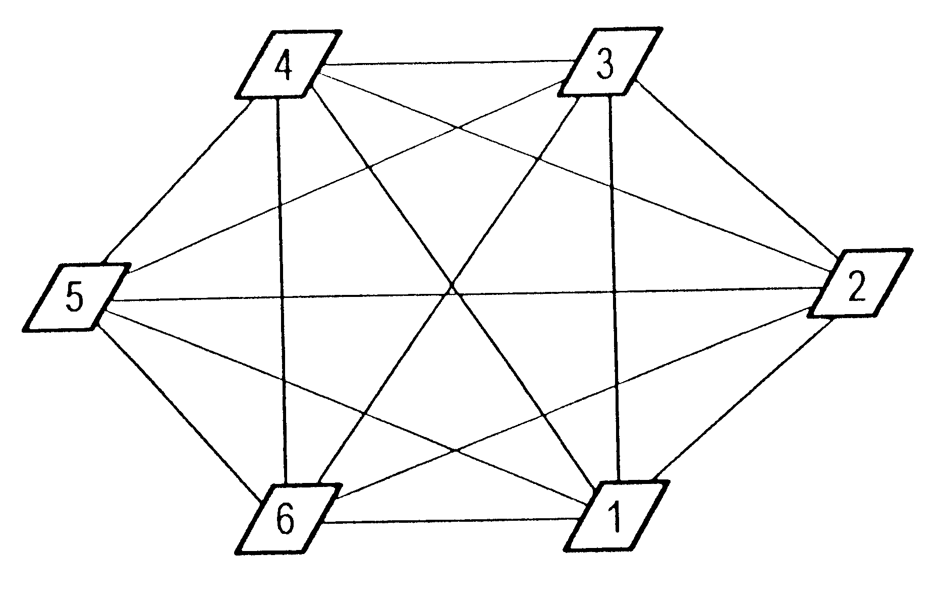
FIG. 1 shows a block diagram of a small, fully interworked network with six network switching nodes 1, 2, 3, 4, 5, and 6 and the corresponding capacities of the path sections or links A, B, C, D, E, F, G, H, I, J, K, L, M, N, and O between the network nodes 1, 2, 3, 4, 5, and 6, whereby a link A, B, C, D, E, F, G, H, I, J, K, L, M, N, and O comprises at least one trunk group.

Let it then be assumed that the switching node 1 has a call for switching node 2 but the direct route of link A between the two switching nodes is not available.

Let it also be assumed that the initial path fan, i.e. the fan of the active alternate paths, comprises three alternate paths after its most recent re-initialization, namely the two-link alternate paths B and F, C and G, D and H via the switching nodes, 3, 4 and 5.

Let it also be assumed that the overflowing traffic is uniformly cyclically distributed onto these active alternate paths B and F, C and G, D and H by the routing system, namely in the sequence...


PUM


Abstract

The dynamic routing of a communication network should adapt to the traffic load existing in the network such that the network throughput is optimized. The inventive routing method solves this problem by a dynamic path fan, with alternate paths, upon whose only specifically selected alternate paths are incorporated.

Description

1. Field of the InventionThe present invention is directed to a method for dynamic traffic routing in a communication network.2. Description of the Prior ArtIn a fully interworked, non-hierarchic network with n network nodes, n-2 alternate paths with only 2 path sections exist for every source-destination pair. Given a lopsided loaded network some of the total of the n.times.(n-1).times.(n-2) alternate paths network-wide are under-loaded and other paths are overloaded.Non-hierarchically organized, line-switching communication networks require dynamic routing that adapts to the traffic load present in the network such that the network throughput is optimized. In particular, lopsided load situations must thereby also be defused by the routing.As in conventional routing in hierarchic networks, an initial attempt is also made in dynamic routing to set up connections via one or more scheduled paths that are usually direct paths. When this is not possible because, for example, all connect...

Claims


Application Information

Patent Timeline
IPC IPC(8): H04Q3/64H04Q3/66
CPCH04Q3/66H04Q2213/13103H04Q2213/13109H04Q2213/13141H04Q2213/13164H04Q2213/13166H04Q2213/13213H04Q2213/13217H04Q2213/13332H04Q2213/13344H04Q2213/13353
Inventor STADEMANN, RAINER
Owner SIEMENS AG
Why Eureka
Try Eureka