Power controls with photosensor for tube mounted LEDs with ballast

a technology of led arrays and power controls, which is applied in the direction of cathode-ray/electron beam tube circuit elements, lighting support devices, etc., can solve the problems of unnecessarily high electric bills for lighting and air conditioning, unnecessarily high electric bills for lighting and heating apparatus, and high cost of electricity. , to achieve the effect of greater control

Inactive Publication Date: 2009-02-17
SIGNIFY HLDG BV
View PDF18 Cites 201 Cited by
  • Summary
  • Abstract
  • Description
  • Claims
  • Application Information

AI Technical Summary

Benefits of technology

[0067]The present continuation-in-part invention includes a power saving device for a light emitting diode (LED) lamp mounted to an existing fixture for a fluorescent lamp having a ballast assembly and LEDs positioned within a tube, and electrical power delivered from the ballast assembly to the LEDs. The LED lamp includes means for controlling the delivery of the electrical power from the ballast assembly to the LEDs, wherein the use of electrical power can be reduced or eliminated automatically during periods of non-use. Such means for controlling can include an on-off switch mounted in the tube, or can also include a current driver dimmer mounted in the tube that regulates the amount of power delivered to the LEDs. A computer or logic gate array controls the dimmer or power switch. A sensor such as a light level photosensor and / or an occupancy sensor mounted external to the tube or internal to the tube can send signals to the computer or logic gate array to trigger a switch or control a dimmer. Two or more such LED lamps with one or more computers or logic gate arrays in network communication with sensors can be controlled, so as to reduce flickering between lamps when illumination areas are being alternately occupied. Preset or manually set timers can control switches or be used in combination with the computer, logic array, and dimmer. A combination of at least one occupancy detection sensor and at least one light level photosensor used together to provide input signals to the computer, logic gate arrays, or switches, will provide the best savings in energy and conservation.
[0068]A prior inventive embodiment disclosed a power saving device that includes a fluorescent luminaire having a ballast assembly and LEDs positioned within a tube and electrical power delivered from the ballast assembly to the LEDs. The LED lamp includes means for controlling the delivery of the electrical power from the ballast assembly to the LEDs wherein the use of electrical power can be reduced or eliminated automatically during periods of non-use. Such means for controlling can include an on-off switch mounted in the tube or can also include a dimmer current driver mounted in the tube that regulates the amount of power delivered to the LEDs. A computer or an array of logic gates can control the dimmer or switches to the LED arrays. A sensor such as an occupancy motion detection sensor mounted external to the tube or within the tube can send signals to the computer, logic arrays, or switches. Two or more such LED lamps with one or more computers in network communication with the sensors can be controlled so as to reduce flickering between lamps when illumination areas are being alternately occupied. Preset or manually set timers can control the switch or be used in combination with the computer, logic gate arrays, switch, and dimmer.

Problems solved by technology

Daylight harvesting is beneficial from two standpoints: sunlight is good for people, and electricity is expensive, both financially and environmentally.
The financial costs of not turning off or dimming electric lights include unnecessarily high electric bills for lighting and for the air conditioning required to remove heat created by lights.
But the total costs go far beyond economics to include eyestrain, because of excessive brightness and even a lessening of emotional and intellectual well-being.
Unlike incandescent lamps, fluorescent lamps cannot be directly connected to alternating current power lines.
Unless the flow of current is somehow stabilized, more and more current will flow through the lamp until it overheats and eventually destroys itself.
Unfortunately, the additive approach does not reduce or eliminate the amount of hazardous mercury in the environment.
More importantly, the additives may not work as effectively in the real world as they do in the laboratory TCLP test.
Therefore, the additives that becomes available during the TCLP test to reduce mercury leaching may not or only partly, do their job in real world disposal.
As a consequence, lamps that rely on additives pass TCLP, but may still have relatively high amounts of mercury leaching out into the environment.
However, the “additive” approach is not a guarantee that only small amounts of mercury will leach into the environment upon disposal.
They have indicated that if lamps with additives were thrown away as non-hazardous waste and are later found to behave differently in the landfill, then the generators and those who dispose of such lamps could potentially face the possibility of having violated the hazardous waste disposal regulation known as RCRA.
Besides the emission of ultra-violet (UV) rays and the described use of mercury in the manufacture of fluorescent lamps, there are other disadvantages to existing conventional fluorescent lamps that include flickering and limited usage in cold weather environments.
No mercury lamps are the best option for the environment and for the end-user that desires non-hazardous lamps.
LED lamps consume less energy than conventional lamps and give much longer lamp life.
Unfortunately, the prior art LED lamp designs used thus far still do not provide sufficiently bright and uniform illumination for general lighting applications, nor can they be used strictly as direct and simple LED retrofit lamps for existing fluorescent lighting fixtures and ballast configurations.
But as mentioned before, none of the disclosed retrofit lamps are designed for use as a retrofit lamp for a fluorescent lighting fixture using the existing fluorescent sockets and ballast electronics.
This configuration has its limitation, because the light output is not evenly distributed away from the center.
In addition, the disclosed configuration of the LEDs limits its use in non-linear and curved housings.
Again, power to the LEDs is provided on one end of the lamp only and cannot be used in either non-linear or curved housings.

Method used


Image

  • Power controls with photosensor for tube mounted LEDs with ballast
  • Power controls with photosensor for tube mounted LEDs with ballast
  • Power controls with photosensor for tube mounted LEDs with ballast

Examples


Embodiment Construction

[0275]Reference is now made to the drawings and in particular to FIGS. 1-10 in which identical of similar parts are designated by the same reference numerals throughout.

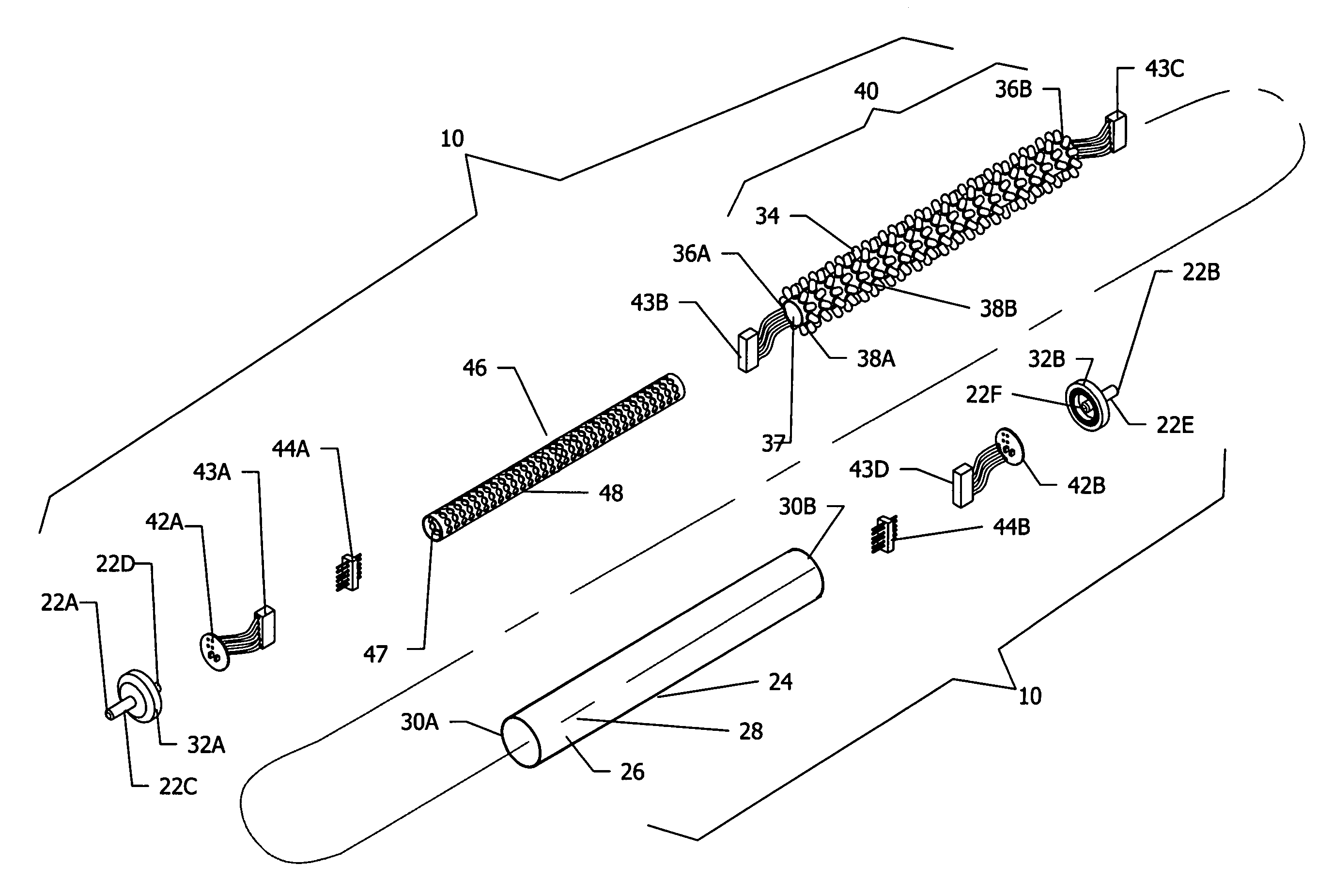
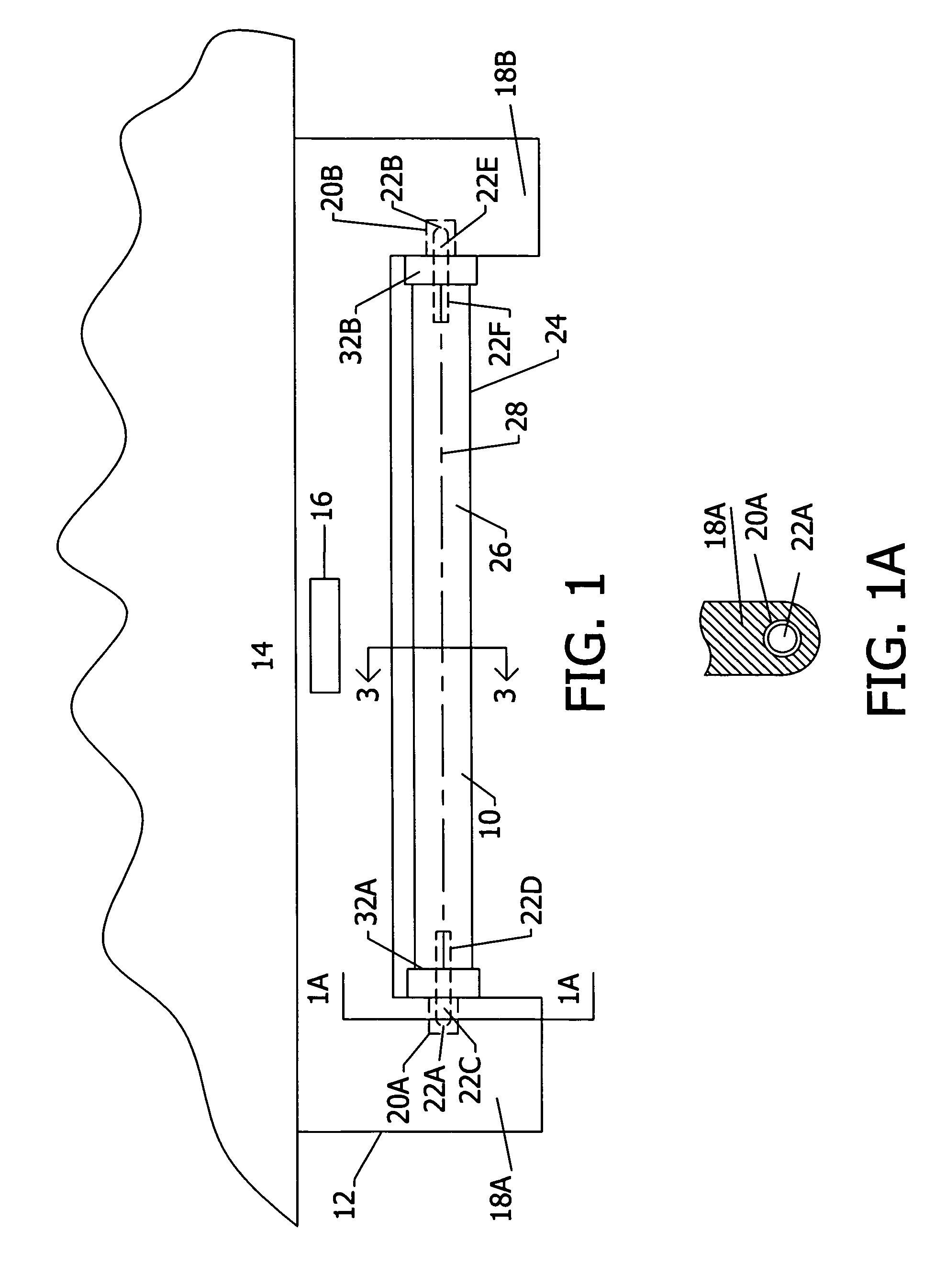
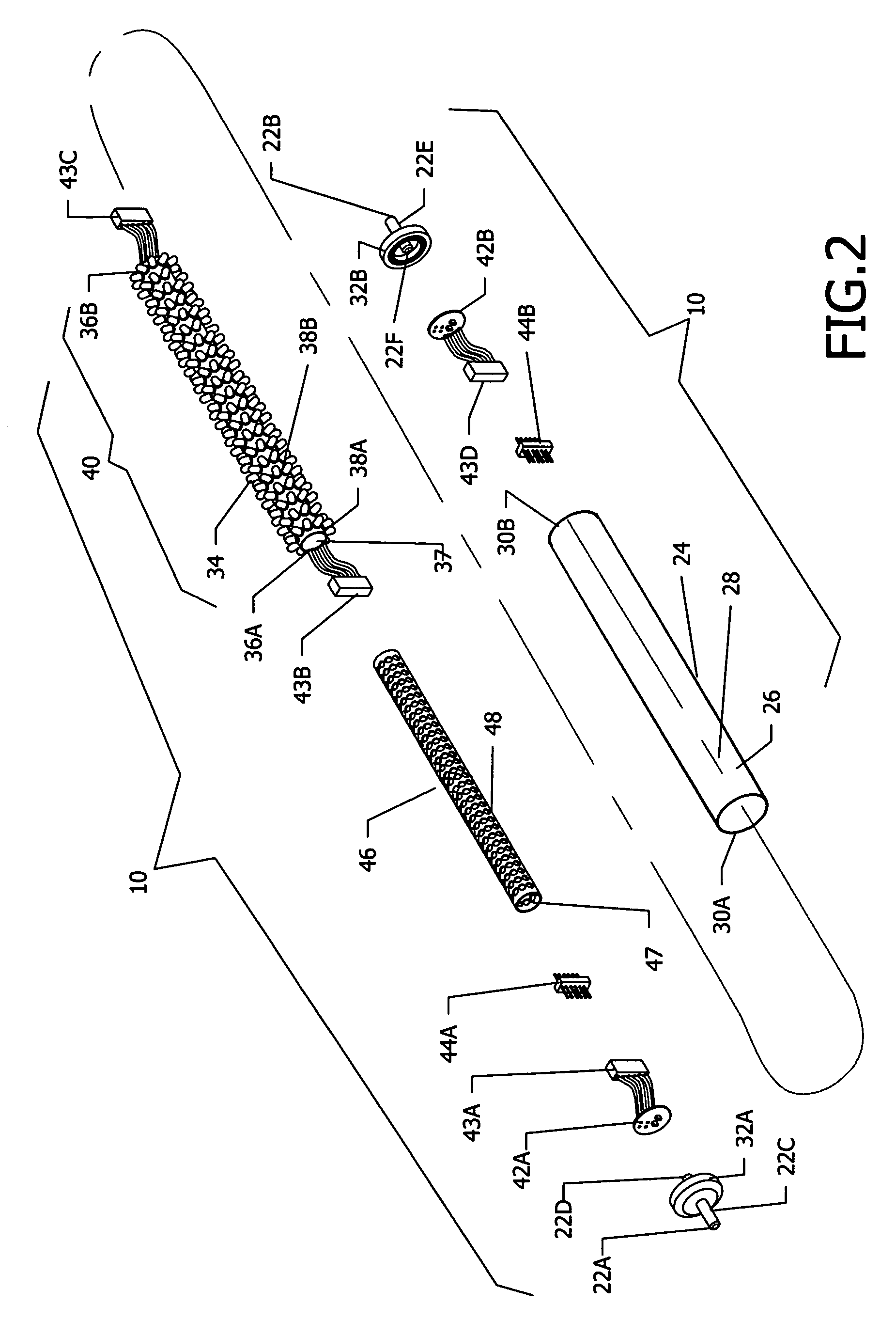
[0276]An LED lamp 10 shown in FIGS. 1-10 is seen in FIG. 1 retrofitted to an existing elongated fluorescent fixture 12 mounted to a ceiling 14. An instant start type ballast assembly 16 is positioned within the upper portion of fixture 12. Fixture 12 further includes a pair of fixture mounting portions 18A and 18B extending downwardly from the ends of fixture 12 that include ballast electrical contacts shown as ballast end sockets 20A and 20B that are in electrical contact with ballast assembly 16. Fixture sockets 20A and 20B are each single contact sockets in accordance with the electrical operational requirement of an instant start type ballast. As also seen in FIG. 1A, LED lamp 10 includes opposed single-pin electrical contacts 22A and 22B that are positioned in ballast sockets 20A and 20B, respectively, so that L...


PUM


Abstract

A power saving device for a light emitting diode (LED) lamp mounted to an existing fixture for a fluorescent lamp having a ballast assembly and LEDs positioned within a tube and electrical power delivered from the ballast assembly to the LEDs. The LED lamp includes means for controlling the delivery of the electrical power from the ballast assembly to the LEDs wherein the use of electrical power can be reduced or eliminated automatically during periods of non-use. Such means for controlling include means for detecting the level of daylight in the illumination area of said least one LED in particular a light level photosensor and means for transmitting to the means for controlling a control signal relating to the detected level of daylight from the photosensor. The photosensor can be used in operative association with an on-off switch in power connection to the LEDs, or with a computer or logic gate array in operative association with a dimmer that controls the power to the LEDs. An occupancy sensor that detects motion or a person in the illumination area of the LEDs can be optionally used in association with the photosensor and the computer and dimmer. Two or more such LED lamps with one or more computers or logic gate arrays can be in network communication with the photosensors and the occupancy sensors to control the power to the LEDs.

Description

HISTORY OF THE INVENTION[0001]This application is a continuation of patent application Ser. No. 11 / 052,328 filed on Feb. 7, 2005, now U.S. Pat. No. 7,067,992 entitled “Power Controls for Tube Mounted LEDs with Ballast”, which is a continuation-in-part of Ser. No. 10 / 822,579 filed Apr. 12, 2004 now U.S. Pat. No. 6,853,151, entitled “LED Retrofit Lamp” issued Feb. 8, 2005, which is a continuation-in-part of Ser. No. 10 / 299,870 filed Nov. 19, 2002 now U.S. Pat. No. 6,762,562, entitled “Tubular Housing with Light Emitting Diodes” issued Jul. 13, 2004.FIELD OF THE INVENTION[0002]The present invention relates to tubular lamps having LED arrays with ballasts.BACKGROUND OF THE INVENTION[0003]U.S. Pat. No. 6,762,562 and U.S. Pat. No. 6,853,151 both set forth LED arrays positioned in tubes that are powered by reduced voltage from a ballast. This reduced voltage can be provided with various controls positioned in the tubes so that the illumination from the LED arrays can be varied or switched ...

Claims


Application Information

Patent Timeline
Patent Type & Authority Patents(United States)
IPC IPC(8): F21K99/00F21V33/00H05B44/00
CPCF21K9/00F21V23/0471H05B33/0803H05B33/0809H05B33/0842H05B33/0851H05B33/0854H05B37/0218H05B37/0227H05B37/0254F21K9/17F21Y2101/02Y02B20/386Y02B20/40Y02B20/44Y02B20/46F21Y2103/003Y10S362/80F21Y2103/025F21K9/27F21Y2103/10F21Y2115/10F21Y2103/37H05B47/11H05B45/3578H05B45/3577H05B47/115H05B45/37H05B45/12H05B47/19H05B47/18Y02B20/30
Inventor LEONG, SUSAN J.KIT, JOHN
Owner SIGNIFY HLDG BV
Why Eureka
Try Eureka