Weight-adjustable dumbbell

a weight-adjustable and dumbbell technology, applied in the field of dumbbells, can solve the problems of time-consuming and inconvenient weight-adjustment operation, and achieve the effect of convenient us

Active Publication Date: 2009-02-17
ASIA REGENT
View PDF19 Cites 98 Cited by
  • Summary
  • Abstract
  • Description
  • Claims
  • Application Information

AI Technical Summary

Benefits of technology

[0005]Therefore, an object of the present invention is to pr

Problems solved by technology

The weight-adjusting operation is t

Method used


Image

  • Weight-adjustable dumbbell
  • Weight-adjustable dumbbell
  • Weight-adjustable dumbbell

Examples


Embodiment Construction

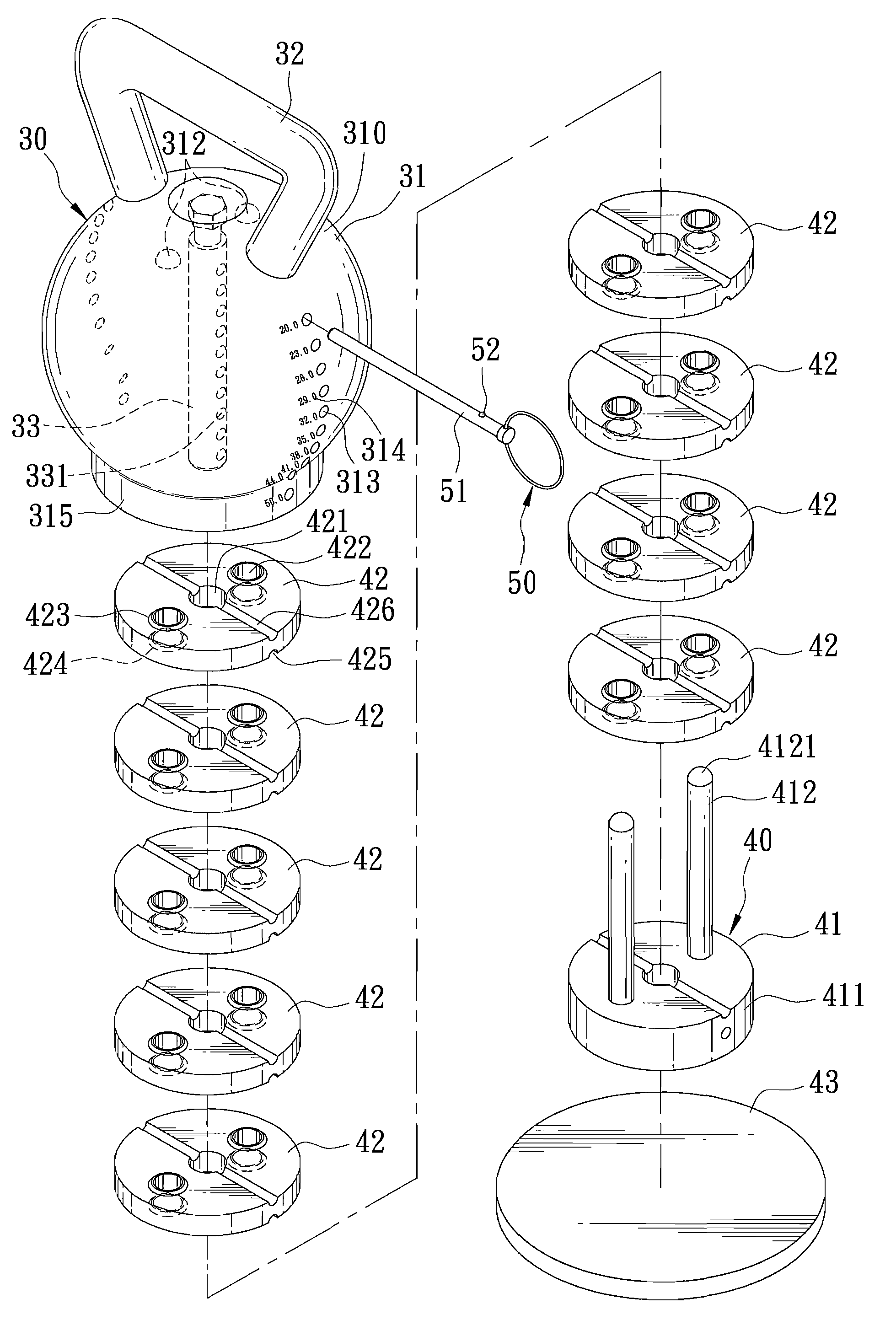
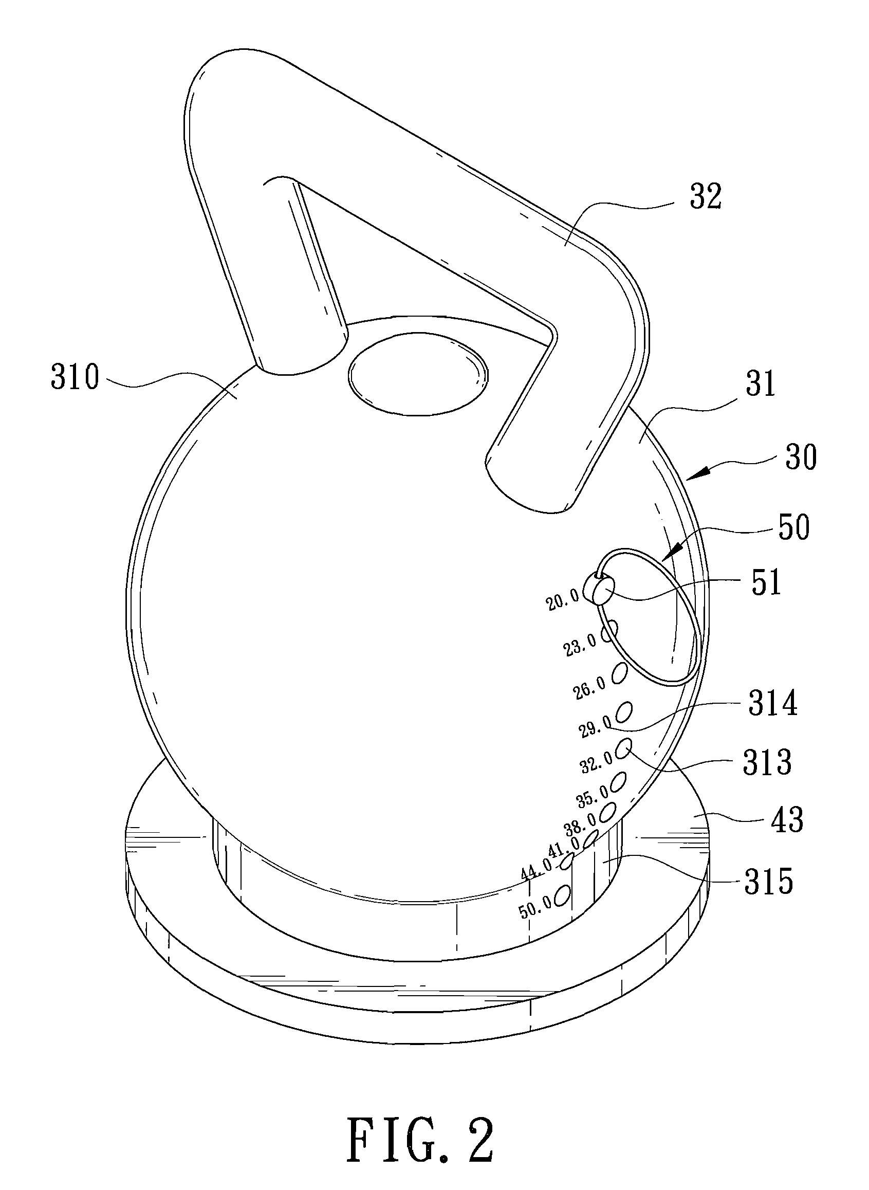
[0017]Referring to FIGS. 2 to 4, the preferred embodiment of a weight-adjustable dumbbell according to the present invention is shown to include a dumbbell shell unit 30, a weight unit 40, and an insert pin unit 50.

[0018]The dumbbell shell unit 30 includes a hollow shell body 31, a weight selector rod 33, and a handle 32. The shell body 31 confines a receiving space 311, and has a top shell portion 310 with an inner side that faces the receiving space 311, and an outer side opposite to the inner side. The shell body 31 further has an open bottom shell portion 315 opposite to the top shell portion 310 in a vertical direction. The weight selector rod 33 has a top rod end connected to the top shell portion 310, extends downwardly from the inner side of the top shell portion 310 into the receiving space 311 of the shell body 31, and is formed with a plurality of through holes 331 spaced apart from each other in the vertical direction. The shell body 31 is formed with a plurality of inse...


PUM


Abstract

A weight-adjustable dumbbell includes a dumbbell shell unit, a weight unit, and an insert pin unit. The dumbbell shell unit includes a shell body confining a receiving space, and a weight selector rod connected to the shell body, extending into the receiving space, and formed with through holes registered with insert holes in the shell body. The weight unit is extended removably into the receiving space via an open bottom of the shell body, and includes a base member provided with two positioning posts, and weight pieces stacked on the base member. Each weight piece is formed with a rod hole for extension of the weight selector rod, and two post holes for extension of the positioning posts. The insert pin unit includes an insert pin inserted removably into a selected insert hole and extending removably through a corresponding through hole in the weight selector rod.

Description

BACKGROUND OF THE INVENTION[0001]1. Field of the Invention[0002]The invention relates to a dumbbell, more particularly to a weight-adjustable dumbbell.[0003]2. Description of the Related Art[0004]Referring to FIG. 1, a conventional weight-adjustable dumbbell 20 is shown to include a plurality of weight pieces 21, a handle 22 disposed above the weight pieces 21, a base plate 23 disposed below the weight pieces 21, a fastener 24, and a plurality of spacers 25. Each of the weight pieces 21 has a predetermined weight and is formed with a central hole 211. The handle 22 includes a grip portion 221 and a weight-coupling portion 222 connected to the grip portion 221. The weight-coupling portion 222 extends through the central holes 211 in the weight pieces 21, and is fastened to the base plate 23 via the fastener 24 that engages a screw hole 223 in the weight-coupling portion 222, thus securing the weight pieces 21 between the handle 22 and the base plate 23. To adjust the weight of the du...

Claims


Application Information

Patent Timeline
IPC IPC(8): A63B21/075
CPCA63B21/0728A63B21/075A63B21/00065A63B21/072
Inventor LIN, WILLIAM
Owner ASIA REGENT
Why Eureka
Try Eureka