Fuel sampler/strainer assembly

a sampler and strainer technology, applied in the field of hand tools, can solve the problems of less than substantial, difficult to store the device, and all the associated inconvenience and time consumption, and achieve the effect of convenient storage and durabl

Inactive Publication Date: 2009-02-17
BRODBECK ROBERT M +1
View PDF24 Cites 5 Cited by
  • Summary
  • Abstract
  • Description
  • Claims
  • Application Information

AI Technical Summary

Benefits of technology

[0012]Use of the present invention has several advantages over the GATs Jar. It is compact and therefore can be easily stowed. The housing is of substationally heavier material making it more durable. The rod can be stowed in either the fuel receiving portion or in the cap for the fuel receiving portion. It is entirely sealable when maintained in a stowed mode. Therefore, fumes and residual fuel cannot leak. The fuel sampler / strainer can be supported on the drain tube of a sump with a remote actuating lever. This is particularly adaptable for use on, for example, a Cessna 172N.

Problems solved by technology

In the past this was accomplished by the use of any convenient instrumentalities, with all the associated inconvenience and time-consumption.
This is undesirable if the sample has water and / or other contaminants.
The GATS Jar; however, has an open end so that while not in use it is difficult to store the device due to the resultant fumes and potential dripping of residual fuel from it.
Furthermore, it includes a plastic plunger that makes it less than substantial.
Additionally, the GATS Jar has synthetic screen that is susceptible to punctures and tears.

Method used


Image

  • Fuel sampler/strainer assembly
  • Fuel sampler/strainer assembly
  • Fuel sampler/strainer assembly

Examples


Embodiment Construction

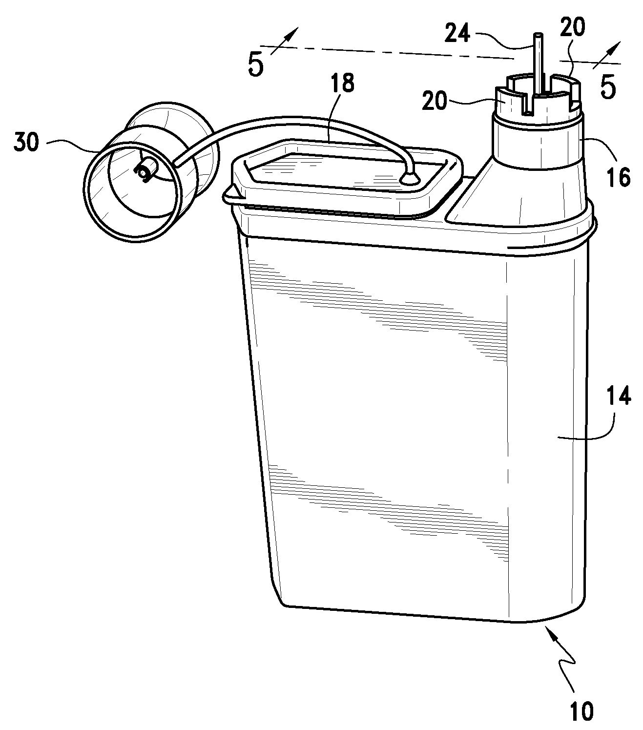
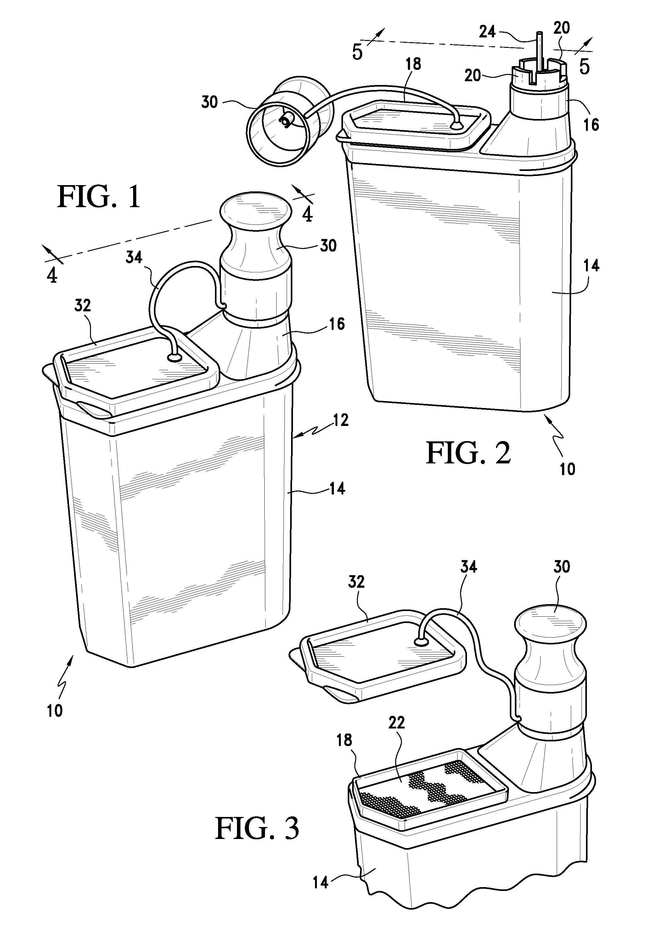
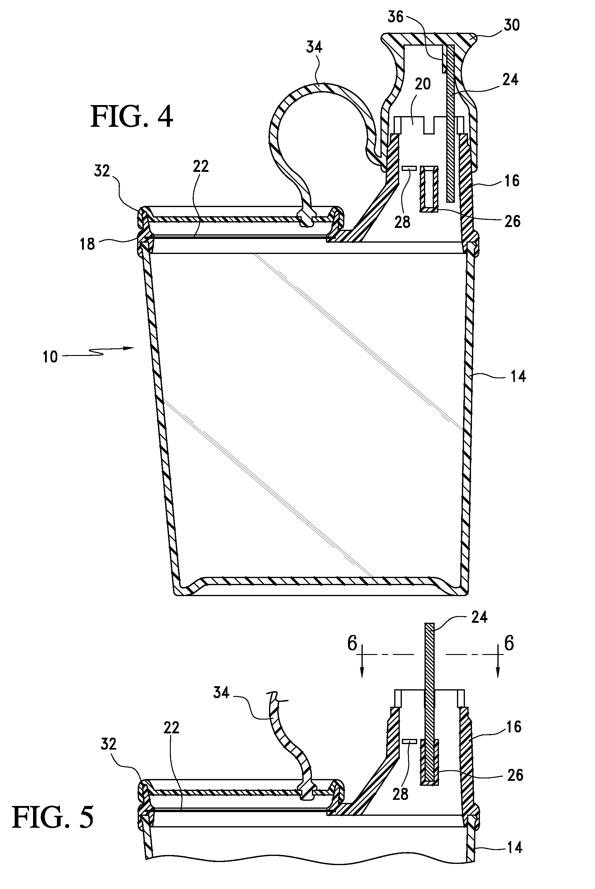
[0020]Referring now to the drawings and the characters of reference marked thereon, FIGS. 1-7 illustrate a preferred embodiment of the fuel sampler / strainer of the present invention, designated generally as 10. The filter assembly 10 includes a housing, designated generally as 12, formed of fuel resistant material. The housing 12 includes a transparent elongated main body 14, a fuel receiving portion 16 at an upper end thereof, and a fuel exiting portion 18 also at the upper end thereof. The fuel exiting portion 18 is spaced from the fuel receiving portion 16. The elongated main body 14 has a closed lower end. The housing 12 preferably includes planar front and back surfaces for optimal stowability.

[0021]As can be seen in FIGS. 2 and 4, the fuel receiving portion 16 is of generally tubular character and communicates with the open upper end of the elongated main body 14. The fuel receiving portion 16 has a plurality of spaced-apart indentations 20 in its upper end edge for alignment ...


PUM

PropertyMeasurementUnit
diameteraaaaaaaaaa
diameteraaaaaaaaaa
diameteraaaaaaaaaa

Abstract

The fuel sampler / strainer assembly includes a housing formed of fuel resistant material including a transparent elongated main body, a fuel receiving portion at an upper end thereof, and a fuel exiting portion also at the upper end thereof. The elongated main body has a closed lower end. The fuel receiving portion is generally tubular and has spaced-apart indentations in its upper end edge for alignment and cooperation with associated actuating arms of a pet cock drain valve. A rod is removably attachable at a first end to the fuel receiving portion and extends along a central axis of the fuel receiving portion and beyond the upper end edge of the fuel receiving portion so as to engage and manipulate a ball and spring drain valve at a second end of the rod. The fuel exiting portion includes a filter screen functioning as a barrier to water and desired particulate debris. A first protective cap fits over the fuel receiving portion for containing evaporative fumes while the fuel sampler / strainer assembly is being stowed. A second protective cap fits over the fuel exiting portion for similar purposes.

Description

BACKGROUND OF THE INVENTION[0001]1. Field of the Invention[0002]The present invention relates to hand tools, and more particularly to a fuel checker designed for use in conjunction with fuel tank valves and incorporating a receptacle for receiving a specimen of the fuel tank contents, and returning the specimen to the fuel tank, while filtering water and contaminants from the fuel, and discarding water and contaminants.[0003]2. Description of the Related Art[0004]As a recognized safety precaution, the nature of the fuel in aircraft gas tanks must be checked before each flight to determine the presence of any contaminating agents as well as the octane rating. In the past, this inspection has been effected by, for example, the opening of the tank quick drain valve, by any suitable means in allowing a portion of the fuel to flow outwardly for reception within any convenient type of container. A scrutiny of the withdrawn fuel by an experienced individual will readily indicate whether th...

Claims


Application Information

Patent Timeline
Patent Type & Authority Patents(United States)
IPC IPC(8): B01D35/02B67D5/58B01D35/34B67D7/76
CPCG01N1/2035G01N1/4077G01N2001/4088
Inventor BRODBECK, ROBERT M.TEILBORG, CHARLES A.
Owner BRODBECK ROBERT M
Why Eureka
Try Eureka