Fiber distribution device for dry forming a fibrous product and method

a fiber distribution device and fiber technology, applied in the direction of manufacturing tools, raw material division, other domestic articles, etc., can solve the problems of limited capacity of the plant, limitation of the length of the fiber used, and generally inability to use fibers with a length of more than 100 mm

Active Publication Date: 2009-02-17
FORMFIBER DENMARK APS
View PDF12 Cites 83 Cited by
  • Summary
  • Abstract
  • Description
  • Claims
  • Application Information

AI Technical Summary

Problems solved by technology

A forming box of the type described in EP 0 159 618 A1 is most often an integral part of the entire papermaking plant, and constitutes an essential limitation to the capacity of the plant.
Thus, there has been a limitation in the length of the fibers used.
In practice, it is found that it is generally not possible to use fibers with a length of more than about 18 mm.
This also limits the kind of non-woven products that can be thus manufactured.
However, clumps of fibers may pass the spike rollers without being tom sufficiently apart by the spikes.
This results in an uneven distribution of fibers on the forming wire.

Method used


Image

  • Fiber distribution device for dry forming a fibrous product and method
  • Fiber distribution device for dry forming a fibrous product and method
  • Fiber distribution device for dry forming a fibrous product and method

Examples


Embodiment Construction

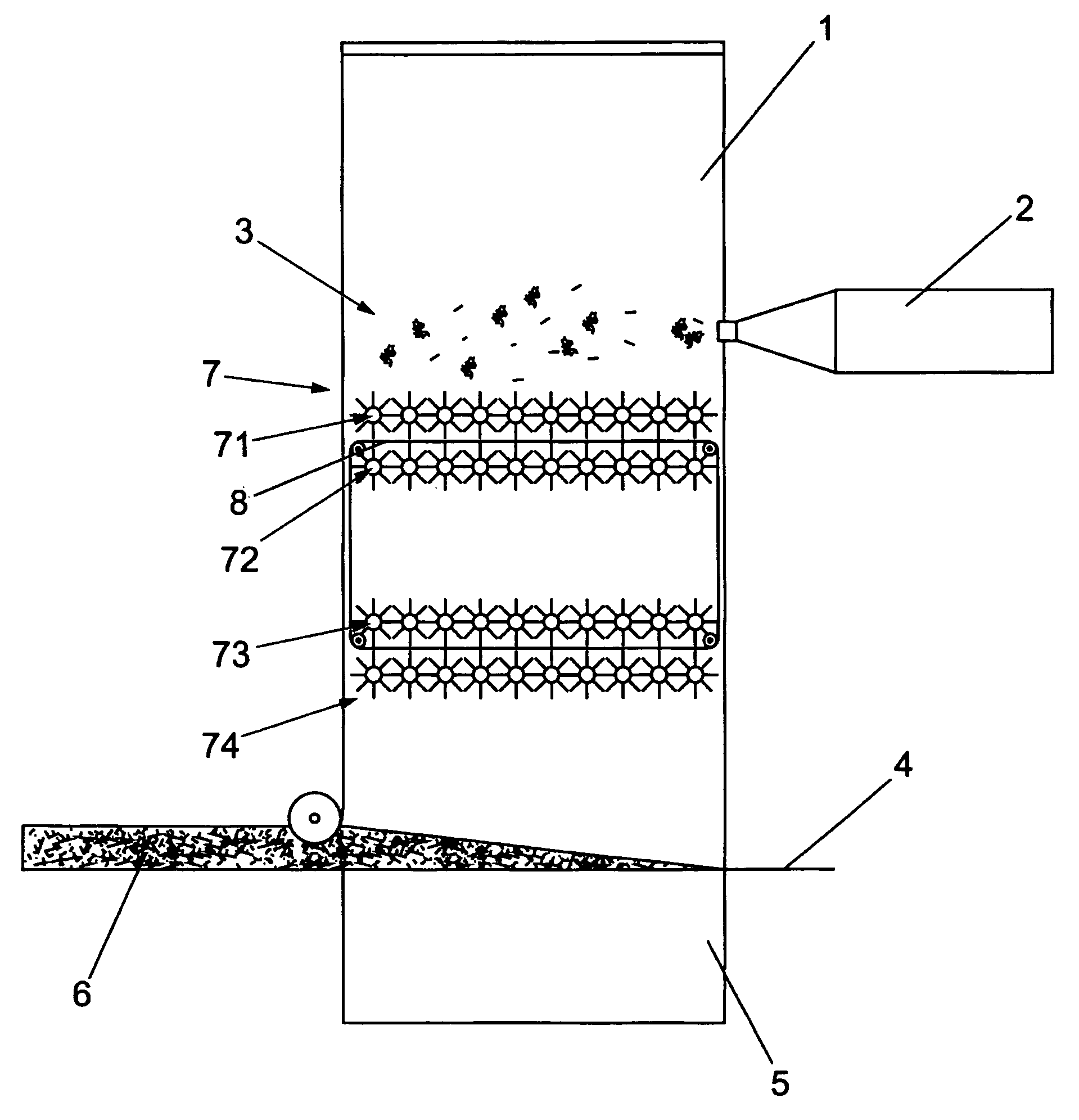
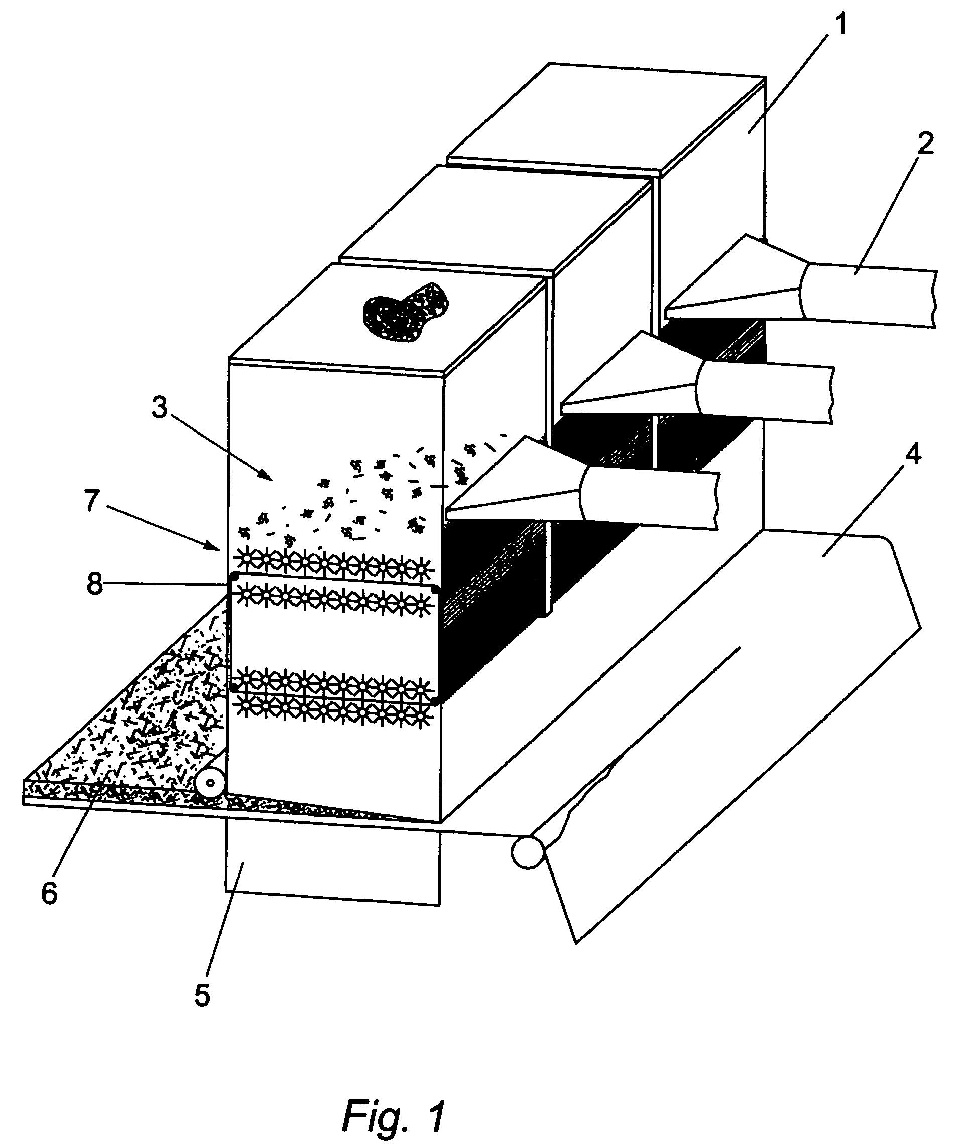
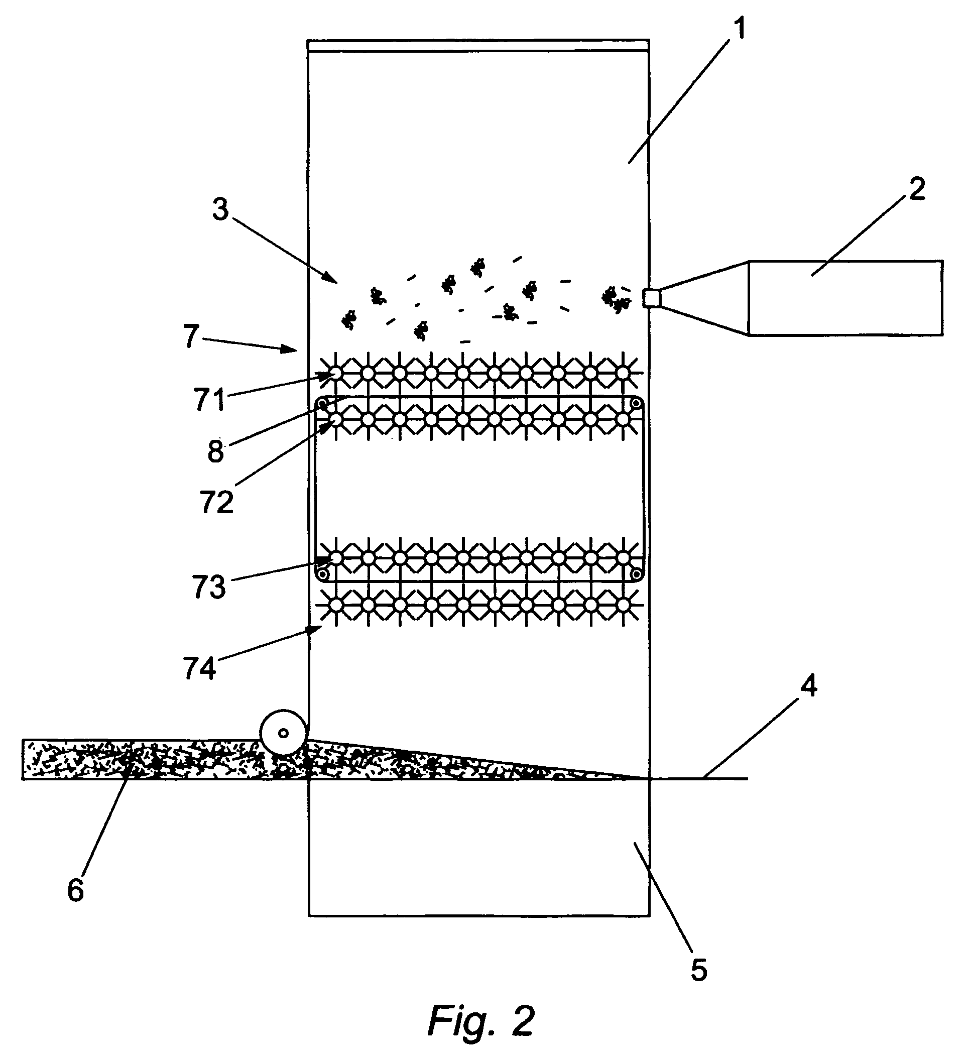
[0023]Use of a forming box according to the invention enables an efficient disintegration of fibers to be achieved and an even distribution of fibers on the forming wire to be obtained by the forming box without reducing the capacity of the fiber distributor. The “forming wire”, as used herein, refers to endless wire screens or other web-like materials of the type used in the paper making industry. An endless belt screen has an upper run, which runs immediately below and / or above a row of spike rollers i.e. for instance between two rows of spike rollers and a lower run in the lower part of the forming box. This promotes an even distribution of the fibers as fiber clumps or oversized fibers are prevented from being laid down on the forming wire but are instead retained on the belt screen in the forming box and transported away from the lower portion of the forming box and returned to the spike rollers for further disintegration. In a forming box according to the invention, the endles...


PUM

PropertyMeasurementUnit
lengthaaaaaaaaaa
movementaaaaaaaaaa
speedaaaaaaaaaa

Abstract

A forming box for use in dry forming of a mat of fibrous material, and a forming method. The forming box comprises a housing with an open bottom providing direct access for fibers onto an underlying forming wire and a vacuum box underneath said forming wire; an inlet for supplying fiber material into the inside of the housing; and a number of fiber separating rollers in one or more rows in the housing between the fiber inlet and the housing bottom. An endless belt screen is provided inside the housing having an upper run between two rows of spike rollers and a lower run closer to the open bottom of the forming box. Fiber clumps captured on the lower run of the belt screen are conveyed above fiber separating rollers and are released from the upper run of the belt screen into contact with the fiber separating rollers.

Description

FIELD OF THE INVENTION[0001]The present invention relates to a forming box for use in dry forming of a mat of fibrous material, and a dry forming method.BACKGROUND OF THE INVENTION[0002]A forming box of the type described in EP 0 159 618 A1 is most often an integral part of the entire papermaking plant, and constitutes an essential limitation to the capacity of the plant.[0003]Fibers are blown into a forming box, where they are distributed onto an underlying forming wire. A vacuum box is provided underneath the forming wire for drawing the fibers onto the forming wire. For placing the fibers on the forming wire, the forming box is provided with a bottom net or sieve having a number of openings. In order to ensure the passage of the fibers through the bottom of the forming box it is suggested to use wings, rollers or other scraping or brushing devices, which in an active manner removes fibers from the sieve at the bottom of the forming box. Although such mechanical devices do give an...

Claims


Application Information

Patent Timeline
Patent Type & Authority Patents(United States)
IPC IPC(8): B27N3/04B07B1/10B27N3/14D04H1/4209D04H1/4218D04H1/70D04H1/732D21F9/00
CPCB07B1/10B27N3/14D04H1/4209D04H1/4218D04H1/70D04H1/732D21F9/00B07B13/18
Inventor ANDERSEN, CARSTEN
Owner FORMFIBER DENMARK APS
Why Eureka
Try Eureka