Method for dynamic flow mapping in a wireless network

Active Publication Date: 2009-02-17
APPLE INC
View PDF10 Cites 32 Cited by
  • Summary
  • Abstract
  • Description
  • Claims
  • Application Information

AI Technical Summary

Problems solved by technology

However, there are problems associated with employing a plurality of service instances concurrently from the MS to the PDSN.
One problem is

Method used


Image

  • Method for dynamic flow mapping in a wireless network
  • Method for dynamic flow mapping in a wireless network
  • Method for dynamic flow mapping in a wireless network

Examples


example

[0069]C->S: INVITE sip:Watson@bell-telephone.com SIP / 2.0[0070]Require: com.example.billing[0071]Payment: sheep_skins, conch_shells[0072]S->C: SIP / 2.0 420 Bad Extension[0073]Unsupported: com.example.billing

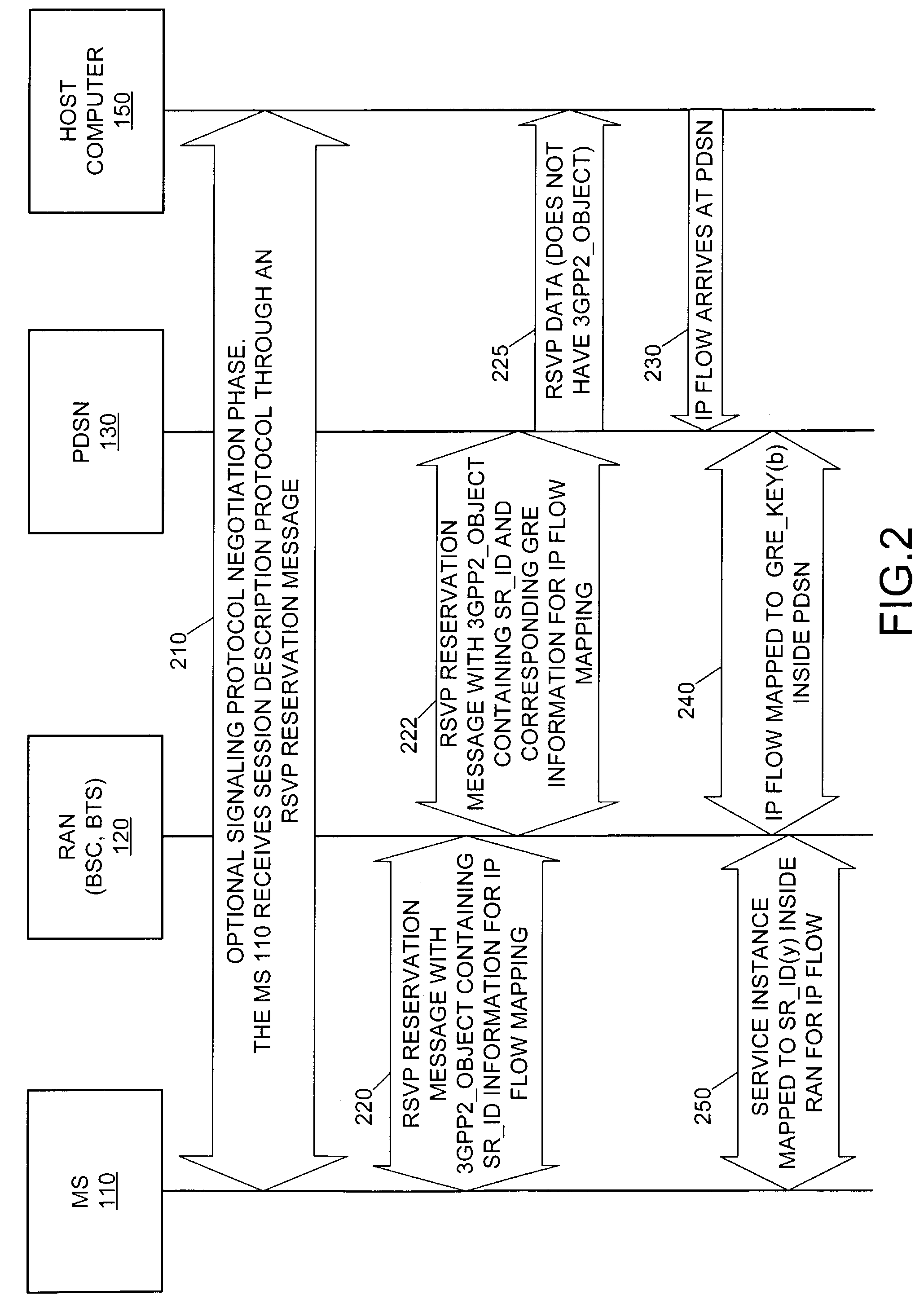
[0074]The PDSN 130 detects the packet header fields containing the RTSP / SIP messages and performs a similar function as described in the bi-directional case. The functions can be the same functions. The RTSP or the SIP message will be formed and initiated by the API in the MS 110 that is responsible for initiating the auxiliary service instance.

[0075]In a second exception to the above table, the MS 110 already has the main service instance setup (in other words, the service instance identifier, SR_ID,=1, the identifier of the main service instance) and the MS 110 has also successfully established a number of auxiliary service instances. The forwarding table in the PDSN 130 is therefore complete and the flows are being mapped based on the entries in the forwarding table. Now, a new ...


PUM


Abstract

The present invention provides for mapping of plurality of IP flows to a plurality service instances. A plurality of IP flows are received at a PDSN. The header information associated with each IP flow at the PDSN is parsed. Each IP flow is mapped to its corresponding service instance. The mapping criteria are defined by a flow filter. The flow filter can be generated within the PDSN, or outside of the PDSN such as by an MS. Each IP flow is transmitted on its corresponding service instance to its endpoint, such as an MS.

Description

CROSS-REFERENCED APPLICATION[0001]This application relates and claims priority from U.S. provisional patent application Ser. No. 60 / 378,026, filed May 13, 2002, entitled “Dynamic IP flow to Service Instance Mapping in the CDMA2000 IP Network,” and further relates and claims priority from U.S. provisional patent application Ser. No. 60 / 387,004, filed Jun. 7, 2002, entitled “Dynamic IP Flow to Service Instance Mapping in the CDMA2000 IP Network,” the contents of which are both incorporated by reference.FIELD OF THE INVENTION[0002]The present invention is generally directed to mapping IP flows to service instances in a CDMA environment and, more particularly, to dynamically mapping IP flows to a Generic Route Encapsulation keys within a Packet Data Service Node.BACKGROUND[0003]A 3GPP2 environment is one in which communication is generally directed to sending a data packet across a wireless media. In conventional systems, a mobile station (MS) attempts to initiate communication with a h...

Claims


Application Information

Patent Timeline
IPC IPC(8): H04L12/28H04B7/216H04L12/56H04L29/06H04L29/08
CPCH04L12/5695H04L29/06H04L47/10H04L47/14H04L47/2441H04L47/2491H04L47/724H04L47/765H04L47/786H04L47/801H04L47/803H04L47/805H04L47/824H04W28/02H04L69/04H04L67/322H04L69/161H04W28/06H04W28/10H04W80/00H04L69/16H04L69/22H04L69/329H04L47/70H04W28/0263H04L67/61H04L9/40H04W8/04
Inventor CHOWDHURY, KUNTAL
Owner APPLE INC
Why Eureka
Try Eureka