Two-tier wireless broadband access network

a wireless broadband and access network technology, applied in the field of wireless access networks, can solve the problems of increasing the packet error rate, limiting the quality, and insufficient number of channel frequencies available to allow each cell, and achieve the effect of optimizing the quality of the concatenated network connection and easy installation

Active Publication Date: 2014-01-07
AMERICAN TELEPHONE & TELEGRAPH CO
View PDF39 Cites 228 Cited by
  • Summary
  • Abstract
  • Description
  • Claims
  • Application Information

AI Technical Summary

Benefits of technology

[0014]A preferred embodiment of the network concatenation device may be referred to as a “window bridge” inasmuch as it can be mounted on the inside of a glass window pane at the premises. The window glass provides a beneficial location for joining the NAN and WLAN networks because neither network experiences significant RF loss penetrating the glass (except for metallic-tinted windows). Accordingly, the window bridge optimizes the quality of the concatenated network connection, while permitting easy installation by a user. For example, a link quality indicator (e.g., bar graph indicator) on the unit can guide the user to the window with the best (strongest) signal from the NAN access point. However, it is to be understood that such a “window bridge” is only an exemplary embodiment of the more general “network concatenation device” of the present invention.
[0015]Advantageously, the utilization of a separate, unique network concatenation device for each home subscriber allows for the present invention to be used for multi-tenant building subscribers in apartments, malls, office parks, campuses, etc. In these multi-tenant situations, each subscriber is individually (but separately) connected to the first tier, neighborhood access point via their own (second tier) network concatenation device. Thus, each subscriber maintains a private, secure connection to the neighborhood access point. This is considered a significant advantage in that it allows separate services to be delivered to a multi-tenant building, where only some of the tenants have subscribed to the service or where there is no Ethernet wiring, or both.

Problems solved by technology

In some environments, however, the number of channel frequencies available is insufficient to allow each cell to operate without experiencing co-channel interference.
This interference limits the quality (i.e., increases the packet error rate) of transmission to stations.
Real-time streaming applications must deliver packets without any accumulation of delays, since delay renders packets useless for reconstitution of source waveforms.
Aside from delays due to errors caused by interference, current arrangements using a WLAN to support voice communications can also be impaired by “contention” when multiple stations attempt to simultaneously transmit their packets.
If the WLAN attempts to service both voice and data communications, the WLAN may not have sufficient capacity (due to the shared nature of the channel) to hold latency below that necessary to prevent interruptions or artifacts in the telephony streams.
Other services, such as video conferencing and real-time streaming IP video, can experience similar difficulties.
Moreover, roaming within a WLAN (between APs) can introduce significant gaps in service, where such gaps also violate the low latency requirements of real-time streaming communication.
Although outdoor operation can extend the cell size to perhaps a radius of 300 feet (with a lowered transmission rate), wireless LANs that attempt to provide both indoor and outdoor coverage experience poor link quality due to the difficulty of propagating RF signals through building walls (which are known to significantly attenuate the signal).
Attempts to use outdoor / indoor single-tier (i.e., single RF link from wired network to station) wireless LAN architectures for service provider local access applications are thus challenged by these issues of signal quality, co-channel interference and the inability to provide deterministic Quality-of-Service (QoS), as particularly required for voice / streaming video applications.

Method used


Image

  • Two-tier wireless broadband access network
  • Two-tier wireless broadband access network
  • Two-tier wireless broadband access network

Examples


Embodiment Construction

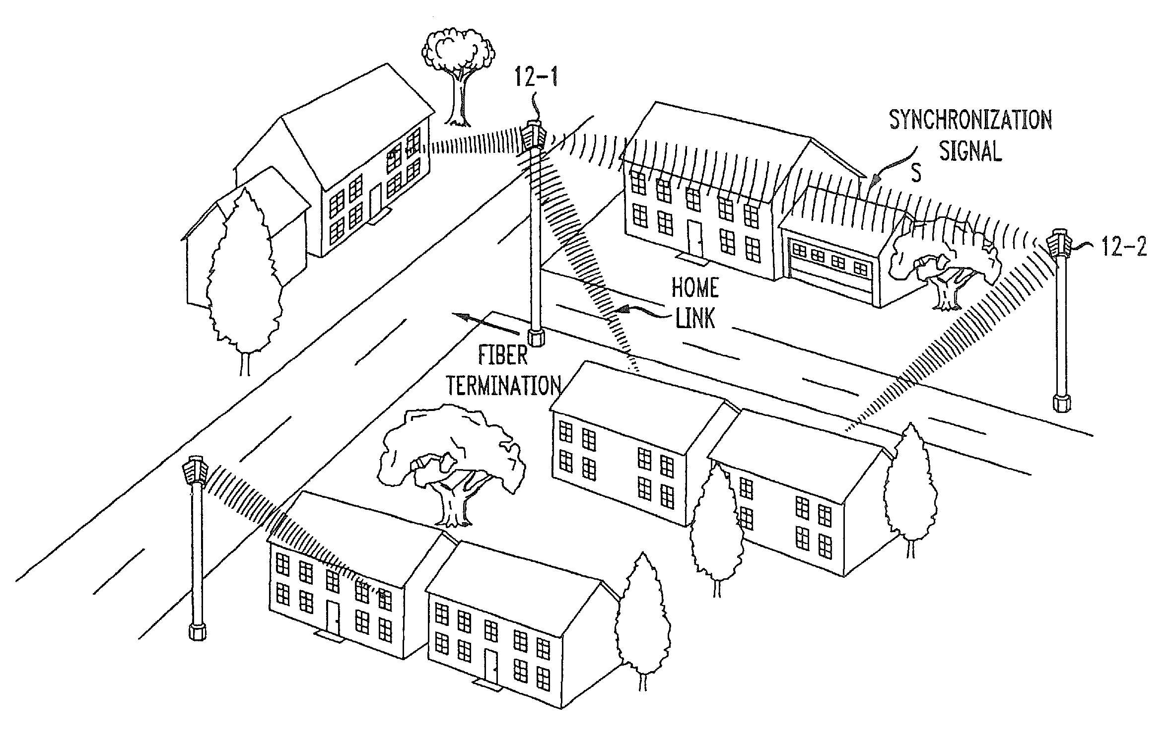
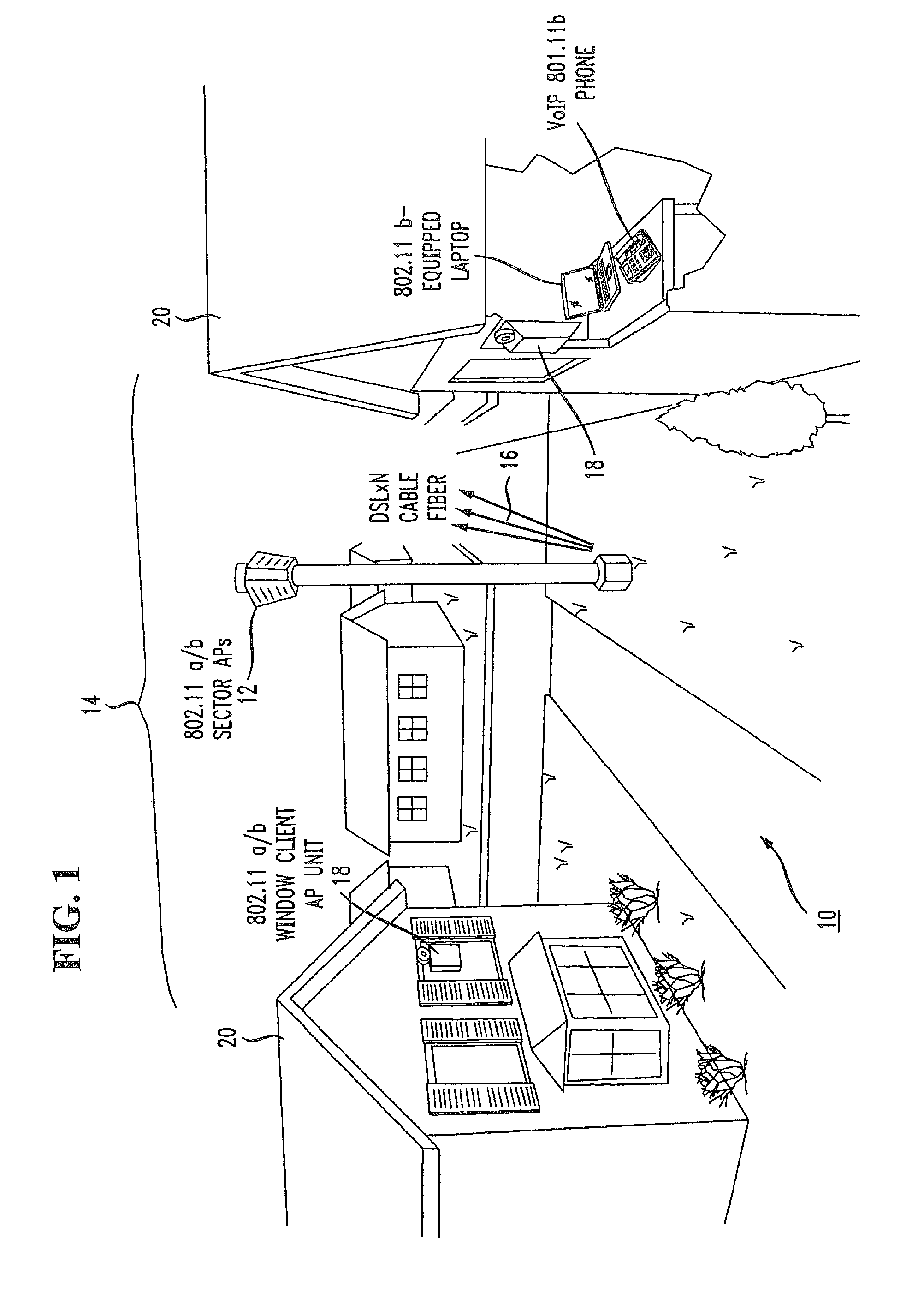
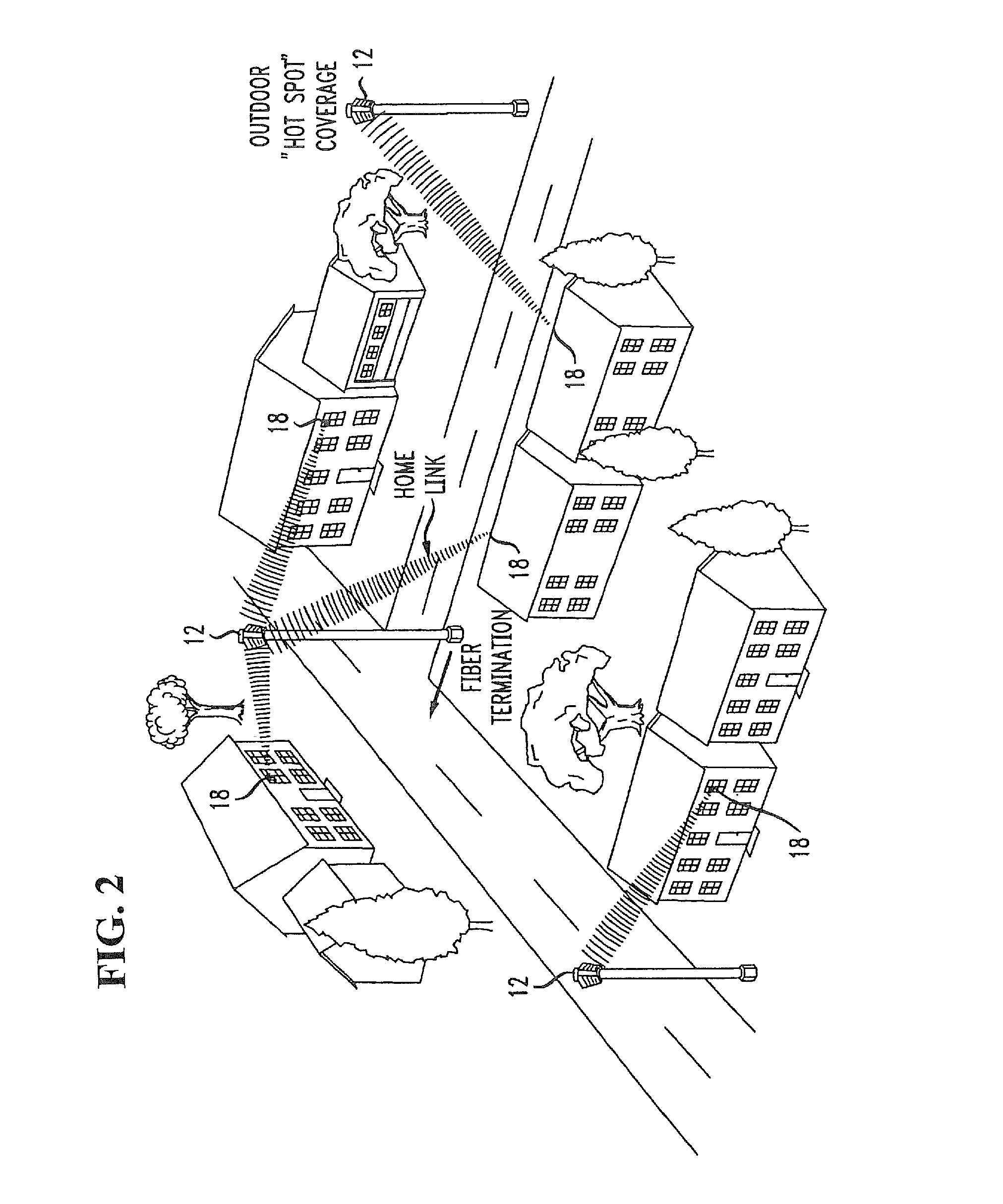
[0026]FIG. 1 illustrates an exemplary arrangement 10 for implementing the two-tier wireless broadband access system of the present invention. As shown, arrangement 10 includes a Neighborhood Area Network (NAN) access point (AP) 12 which is (preferably) centrally disposed within a nanocell 14, the nanocell itself composed of multiple sectors defined by separate APs and associated directional antennas. Each sector is capable of transmitting / receiving relatively low power signals (compatible with license-free operation) with AP 12. For example, each AP 12 may “illuminate” a segment area covering a radius of 1000 feet (or less). In a typical neighborhood, therefore, a single wireless AP 12 may communication with a relatively few houses (or buildings). FIG. 2 contains a simple diagram of an exemplary residential setting in which a plurality of NAN APs 12 are used to provide communication within a neighborhood.

[0027]Wireless AP 12, as shown in FIG. 1, can be installed within a device simi...


PUM


Abstract

A wireless access network is based on a two-tier access point (AP) structure to provide effective and efficient wireless communication into an individual home / office building. A first tier of the network utilizes “neighborhood” APs, relatively low power, and utilized to provide wireless communication with a “nanocell” boundary (e.g., 300-1000 feet). A second tier of the network utilizes a set of “network concatenation devices” (window bridge), with a separate network concatenation device at each permanent facility in the nanocell that houses wireless devices. The network concatenation device is attached to a window, for example, of a home in communication with the neighborhood AP. The network concatenation device functions as a bridge to couple to each of the wireless devices within the home. This communication is then relayed in an efficient manner between the network concatenation device and the neighborhood AP. By using a number of neighborhood APs, rather extensive wireless coverage can be obtained.

Description

CROSS-REFERENCE TO RELATED APPLICATIONS[0001]This application claims the benefit of U.S. Provisional Applications 60 / 660,786 filed Mar. 11, 2005 and 60 / 661,567 filed Mar. 14, 2005.TECHNICAL FIELD[0002]The present invention relates to wireless access networks and, more particularly, to the utilization of a two-tier access network useful in providing communication between a neighborhood access point (first tier) and a residence / office access point (second tier), with a network of the first tier access points then coupled into one or more backbone communication networks.BACKGROUND OF THE INVENTION[0003]Wireless LANs (WLANs) are defined as wireless networks that provide inexpensive, high-speed, wireless communications in office buildings, the home, public areas, and a variety of commercial and industrial locations. A “STAtion” (STA) in a WLAN can be a personal computer, a bar code scanner, or other mobile and / or stationary devices with the appropriate integrated chip set or wireless net...

Claims


Application Information

Patent Timeline
Patent Type & Authority Patents(United States)
IPC IPC(8): H04B7/00H04W4/00H04W4/021
CPCY02D30/70H04W92/02H04W84/12H04W4/021H04B7/026
Inventor MILLER, II, ROBERT, RAYMOND
Owner AMERICAN TELEPHONE & TELEGRAPH CO
Why Eureka
Try Eureka