
Path selection in wireless networks

a wireless network and path selection technology, applied in the field of path selection in wireless networks, can solve the problems of affecting the overall system communication capacity, the discovery process of a wireless node is relatively complicated, and the source of interference is dominant, so as to achieve the lowest total cost

Active Publication Date: 2007-05-08
APPLE INC
View PDF12 Cites 228 Cited by
  • Summary
  • Abstract
  • Description
  • Claims
  • Application Information

AI Technical Summary

Benefits of technology

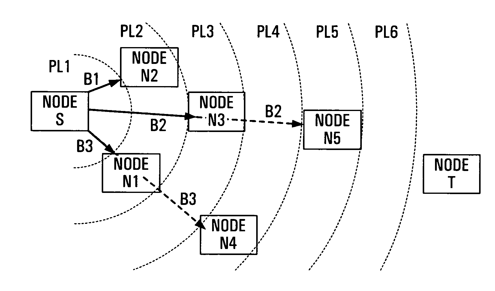
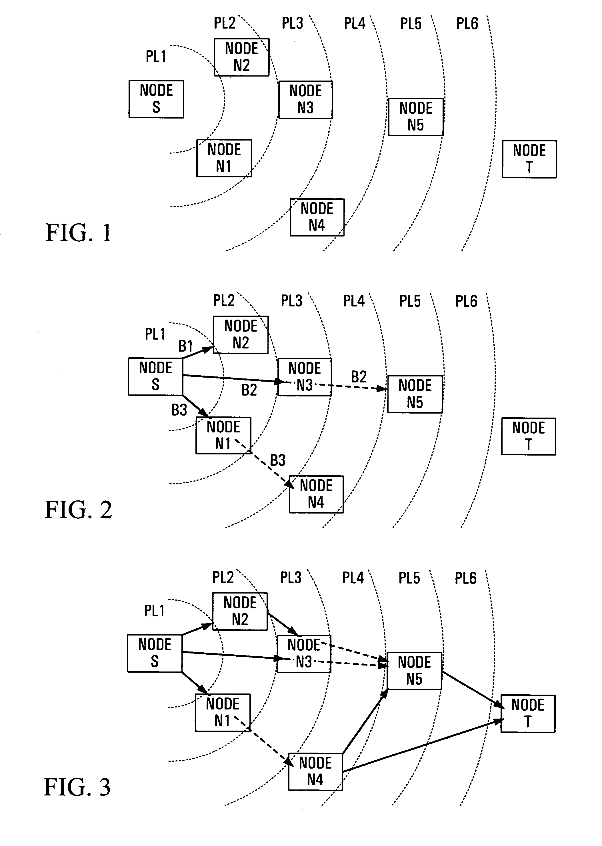
[0032]According to this invention there is provided a method of selecting a communication path, in a wireless network comprising a plurality of nodes and wireless communication links between the nodes, from a plurality of potential communication paths comprising different combinations of said links from a source node to a target node, comprising the steps of, in the source node: determining for each link in the potential communication paths a cost of interference dependent upon a number of nodes affected by a signal sent via the respective link; determining a total cost for each potential communication path, the total cost being dependent upon combined costs of interference for the links of the respective potential communication path; and selecting as a communication path from the source node to the target node a potential communication path having a lowest total cost.

Problems solved by technology

Accordingly, the discovery process for a wireless node is relatively more complicated.
However, in many wireless networks the overall system communication capacity is limited by the amount of interference that each node in the network encounters.
While part of such interference may be from sources external to the wireless network, wireless communications of other nodes within the network are a significant, and often dominant, source of interference.
This interference is increased with higher power signals transmitted from the nodes.
With increasing distances between the two nodes, for example if the terminals are far apart, the first node must use an increasing transmit power level, contributing to increased interference for other nodes in the network.
Such coordination introduces communications overhead and further interference, and so there is a further trade-off between the coordination overhead and the benefits of coordination.

Method used


Image

  • Path selection in wireless networks
  • Path selection in wireless networks

Examples


Embodiment Construction

[0044]Referring to the drawings, FIG. 1 illustrates parts of a wireless access network having distributed nodes which are assumed to use omnidirectional antennas for communications between nodes via wireless communication paths or transit links as described above. By way of example, FIG. 1 shows a source node S, a target node T, and other nodes N1 to N5 which are distributed within a geographical region or service area.

[0045]Preferably, this service area is a wireless access service area within which wireless terminals, not shown and which may have any of various forms, can communicate with the nodes to which they are closest thereby to communicate for example with other terminals within the service area or with a wired network (not shown) to which at least one of the nodes can be connected.

[0046]However, the invention is not limited to this application, and applies to any communications between nodes of a wireless network regardless of the sources and destinations of signals to be ...


PUM


Abstract

In a wireless network, a lowest cost path from a source node to a target node is selected from a plurality of potential paths. The source node sums costs for the links of each potential path. For each link, these costs include a cost of interference, dependent on a number of nodes affected by a signal sent via the respective link. The link costs can also include a cost of transmission, dependent upon a data rate for the respective link, and a cost of coordination for transmissions with other nodes of the network.

Description

CROSS-REFERENCE TO RELATED APPLICATIONS[0001]This application claims the benefit of U.S. Provisional Application No. 60 / 467,432 filed May 2, 2003, the entire contents and disclosure of which are hereby incorporated herein by reference.[0002]This patent application is related to the following Provisional patent applications filed in the U.S. Patent and Trademark Office, the disclosures of which are expressly incorporated herein by reference:[0003]U.S. Patent Application Ser. No. 60 / 446,617 filed on Feb. 11, 2003 and entitled “System for Coordination of Multi Beam Transit Radio Links for a Distributed Wireless Access System” [15741][0004]U.S. Patent Application Ser. No. 60 / 446,618 filed on Feb. 11, 2003 and entitled “Rendezvous Coordination of Beamed Transit Radio Links for a Distributed Multi-Hop Wireless Access System” [15743][0005]U.S. Patent Application Ser. No. 60 / 446,619 filed on Feb. 12, 2003 and entitled “Distributed Multi-Beam Wireless System Capable of Node Discovery, Redisc...

Claims


Application Information

Patent Timeline
Patent Type & Authority Patents(United States)
IPC IPC(8): H04B1/00H04B15/00H04B7/005H04L12/28H04L12/56H04W40/16
CPCH04W40/16
Inventor GAGE, WILLIAMMUKHERJEE, BISWAROOP
Owner APPLE INC
Learn More