
Intake and plucking arrangement

a technology applied in the field of intake and plucking arrangement, can solve the problems of difficult transfer of overripe and soft stalks into the plucking assembly, and achieve the effect of improving the quality of the plucking assembly

Inactive Publication Date: 2009-02-24
MASCHFAB KEMPER
View PDF16 Cites 15 Cited by
  • Summary
  • Abstract
  • Description
  • Claims
  • Application Information

AI Technical Summary

Benefits of technology

[0005]The present intake and plucking arrangement comprises a rotatable intake device that grasps parts of the standing plants and directs them into a plucking slot. The intake device is preferably provided with a relatively broad operating width; it thereby operates independent of rows. In addition to the intake device, a driven conveying element is arranged upstream and above the intake end of the plucking slot. The plants transported by the intake device to the intake end of the plucking slot come into contact with the conveying element, before they have reached the plucking slot. The conveying element conveys the plants, in conjunction with the intake device, into the plucking slot. Preferably the direction of conveying of the conveying element and the longitudinal direction of the plucking slot are parallel, so that the conveying element can introduce the plants into the plucking slot without any problems.
[0006]The conveying element facilitates the introduction of the plants into the plucking slot. This is especially important respecting plants having soft stalks as the conveying element provides additional support and conveying action to the plants. Due to the supporting effect of the conveying element, a buckling or squashing of the plants between the intake device and the edge of the plucking slot need not be feared.
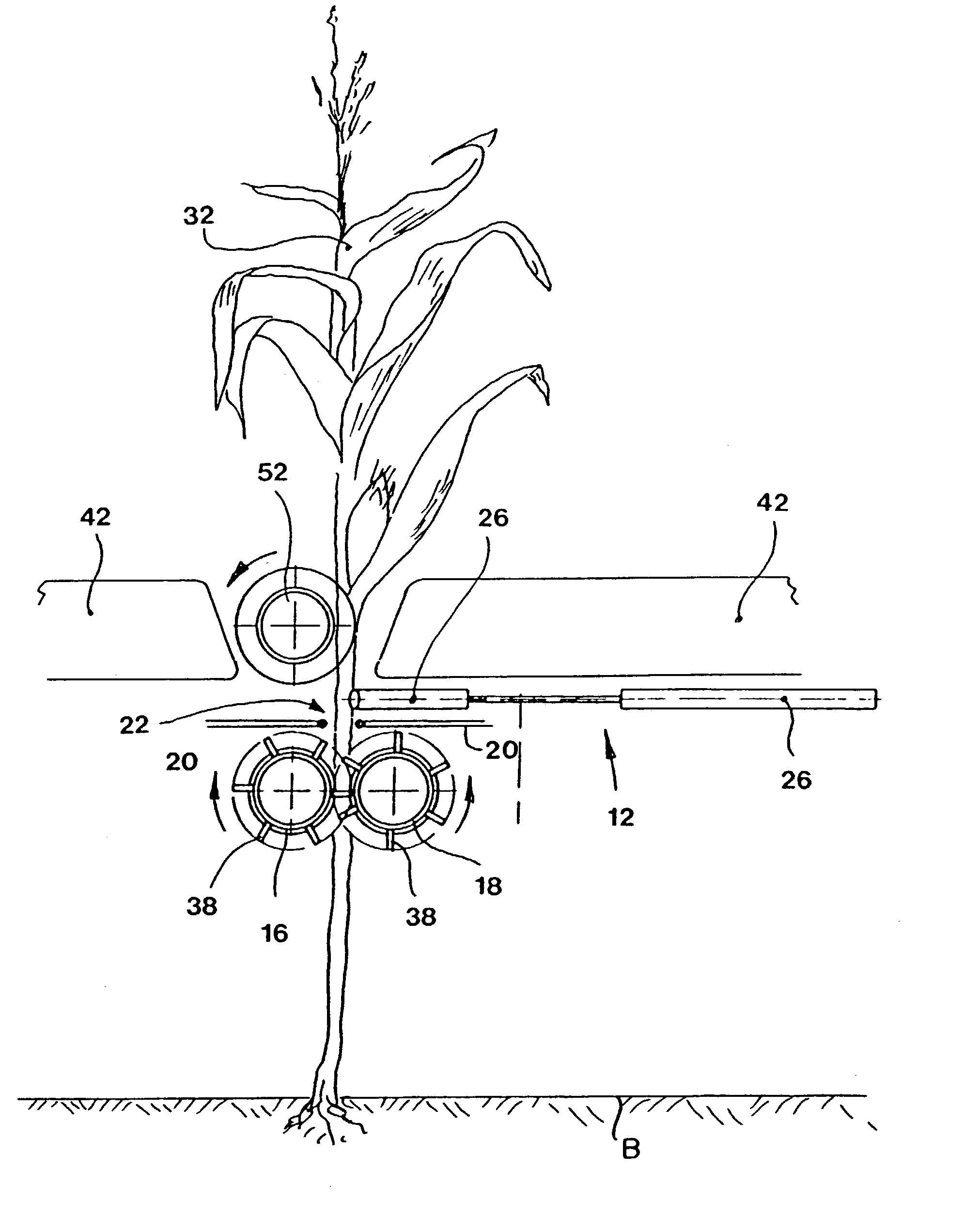
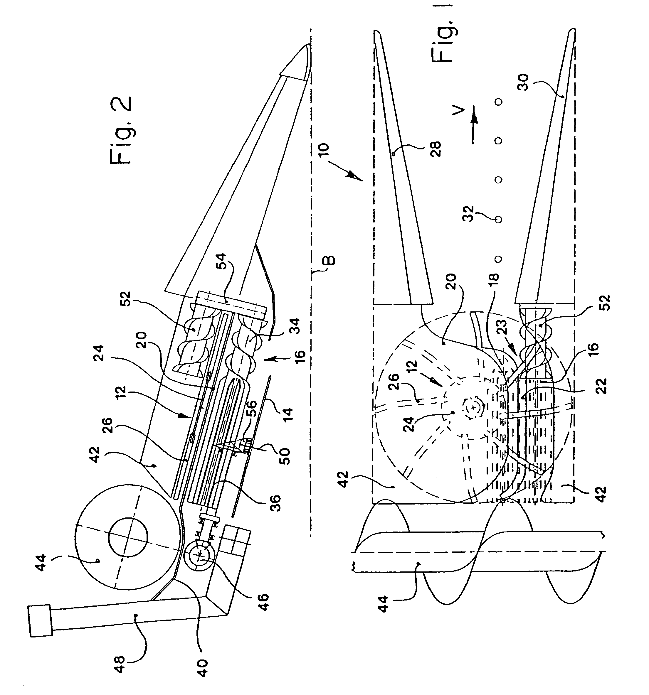
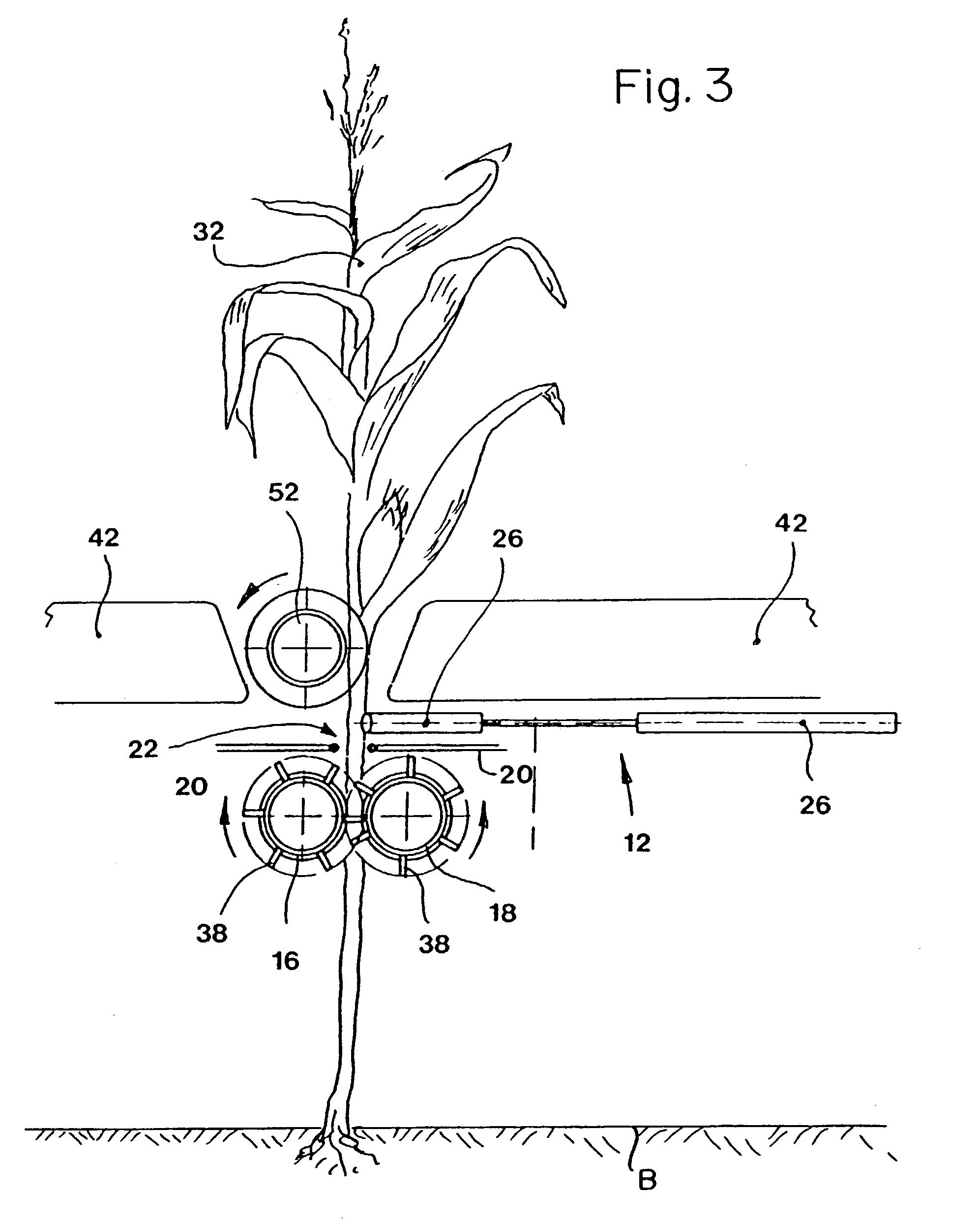
[0012]In order to further improve the introduction of the plants into the plucking slot it is proposed that the plucking device be equipped with a stalk roll that is provided with a region arranged upstream in the direction of movement of the plants in which a screw conveyor is arranged, which also transports the plants that come into contact with it into the plucking slot. The conveying element is arranged above the screw conveyor. As a result, a plant is conducted into the plucking slot by the screw conveyor of the stalk roll, by the conveying element and by the intake device. Therefore the plant is supported at three points so that a buckling even of soft plants need not be feared. As a rule, the conveying speed of the conveying arrangement, of the screw conveyor and of the intake device coincide, so that the plant is conveyed in a vertical position and is not bent due to differing conveying speeds.
[0016]The fingers of the intake device are preferably provided with leading surfaces with rejecting conveying performance, that is, they have a trailing configuration. This conveying performance can be attained by a curvature of the fingers of the intake device that is trailing, opposite to the direction of rotation. Thereby this results in the stalks of the plants being forced outward by the intake device and prevents the stalk from being drawn inward aggressively and becoming clamped between the edge of the sheet metal stripper plate and the finger.

Problems solved by technology

The disadvantage here is seen in the fact that the transition of overripe and soft stalks into the plucking assembly may prove to be problematic.

Method used


Image

  • Intake and plucking arrangement
  • Intake and plucking arrangement
  • Intake and plucking arrangement

Examples


Embodiment Construction

[0020]FIG. 1 shows an intake and plucking arrangement 10 of a crop harvesting arrangement. Typically, a full crop harvesting arrangement is provided with a multitude of intake and plucking arrangements 10. However, it is conceivable that a crop harvesting arrangement could be provided with only a single intake and plucking arrangement 10. If several intake and plucking arrangements 10 are applied, they may be configured identically or symmetrically about the longitudinal center plane of the crop harvesting arrangement.

[0021]The intake and plucking arrangement 10 is provided with an upper intake device 12, that is used for grasping and drawing in the plants that are to be harvested, a rotating chopper knife 14, a first stalk roll 16, a second stalk roll 18 and a sheet metal stripper plate 20 having a plucking slot 22 formed therein. Both stalk rolls 16 and 18 are located below the plucking slot 22.

[0022]The upper intake device 12 is arranged so as to rotate about a vertical axis and ...


PUM


Abstract

An intake and plucking arrangement comprises a rotatable intake device that grasps a standing plant and directs it to a plucking gap. The plucking gap is located above parallel first and second stalk rolls that pull the stalk of the plant downwardly so that the plucking gap can separate the useful parts of the plant from the stalk. The upstream end of the first stalk roll is provided with a lower screw conveyor. A conveyor element is drivingly connected to the screw conveyor. The conveying element comprises an upper screw conveyor that is located above the lower screw conveyor. Both screw conveyors are located upstream from and above the inlet end of the plucking slot. The conveying element working in conjunction with the rotatable intake device direct standing plants into the plucking slot.

Description

[0001]This is a continuation of abandoned application Ser. No. 09 / 873,004, filed Jun. 1. 2001.FIELD OF THE INVENTION[0002]The present invention is directed to an intake and plucking arrangement, having a rotating intake device and an additional conveying element driven by a first stalk roll for directing standing plants into a plucking slot.BACKGROUND OF THE INVENTION[0003]DE 197 34 747 A describes a corn harvesting implement for attachment to a self-propelled harvesting machine that mows plants standing on a field independent of rows and plucks the ears of corn from the plants. For grasping and mowing of the plants independent of rows, the implement is equipped with a mower head with a rotating drum provided on its outer circumference with recesses and a knife rotating below it, as is known practice from corn heads. The plants are conducted to conventional plucking assemblies attached downstream of the mower head. Clean-up disks or points of the plucking rolls penetrating into the ...

Claims


Application Information

Patent Timeline
IPC IPC(8): A01D34/00A01D45/02
CPCA01D45/021
Inventor WUBBLES, RICHARDWOLTERS, NORBERT
Owner MASCHFAB KEMPER
Learn More