Control system design for a mixing system with multiple inputs

a control system and input technology, applied in the direction of sealing/packing, instruments, borehole/well accessories, etc., can solve the problems of lag times, inability to monitor parameters, and difficulty in stabilizing the system

Active Publication Date: 2009-02-24
HALLIBURTON ENERGY SERVICES INC
View PDF65 Cites 72 Cited by
  • Summary
  • Abstract
  • Description
  • Claims
  • Application Information

AI Technical Summary

Problems solved by technology

However, because such systems conventionally control the output parameters, such as cement mixture flow rate and density, dependently, these systems tend to have long lag times in the response of one valve to changes in the position of the other valve.
This can lead to unacceptable oscillations in the monitored parameters, and difficulty in stabilizing the system.

Method used


Image

  • Control system design for a mixing system with multiple inputs
  • Control system design for a mixing system with multiple inputs
  • Control system design for a mixing system with multiple inputs

Examples


Embodiment Construction

[0032]It should be understood at the outset that the present disclosure describes various implementations of different embodiments of a control system having one or more inputs. However, the present control system may also be implemented using any number of other techniques, whether currently known or in existence. The present disclosure should in no way be limited to the descriptions, drawings, and techniques illustrated below, including the design and implementation illustrated and described herein.

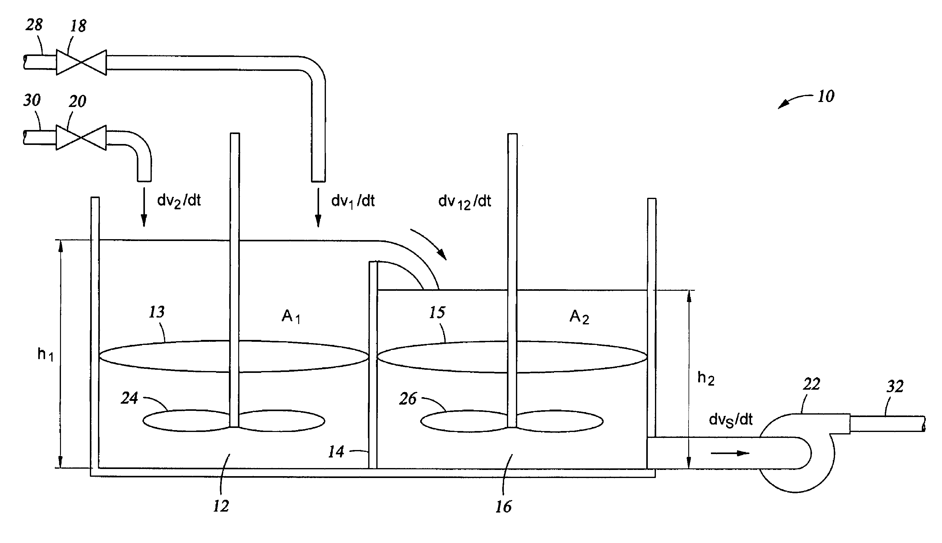
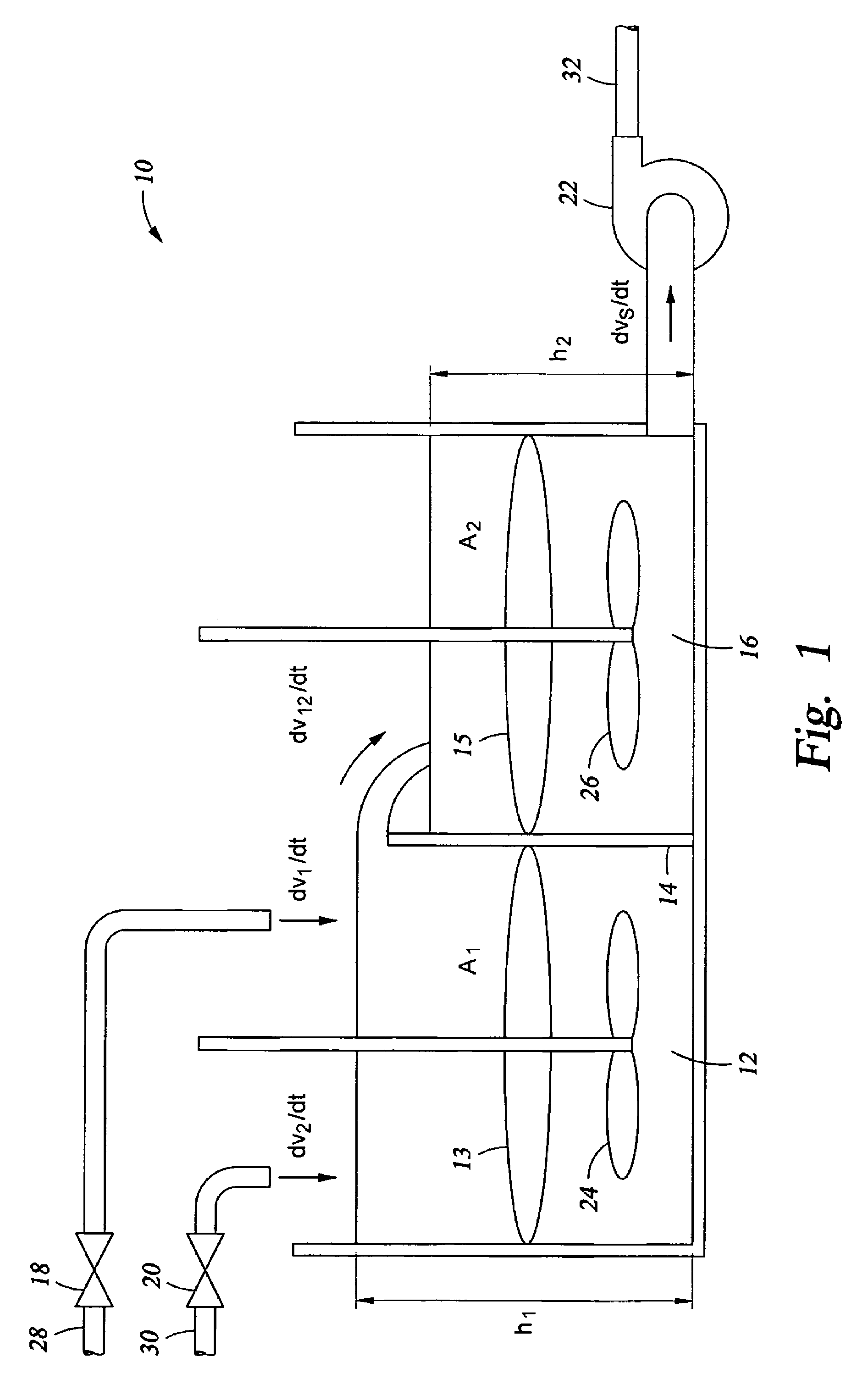
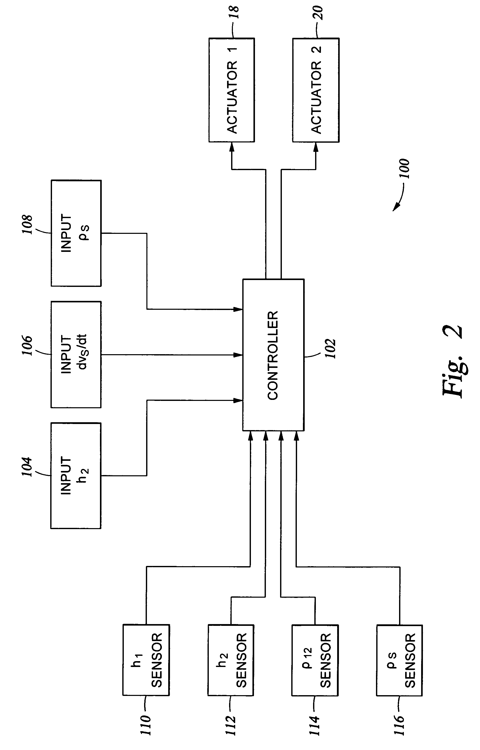
[0033]In an embodiment shown in FIG. 1, a physical plant 10 to be controlled comprises a first tank 12 joined by a weir 14 to a second tank 16, a first actuator 18 dispensing a first material to be mixed, a second actuator 20 dispensing a second material to be mixed, and an outflow pump 22. A first mixture 13 is formed from the in-flow of the first material from the first actuator 18 and the second material from the second actuator 20 into the first tank 12. When the first mixture 13 fi...


PUM

PropertyMeasurementUnit
physicalaaaaaaaaaa
densityaaaaaaaaaa
volume flow rateaaaaaaaaaa

Abstract

A control system for mixing at least two materials in a physical system having two or more tanks comprises at least two actuators, each actuator being operable to introduce a material into a first tank to form a first mixture, the first mixture flowing into a second tank to form a second mixture and a controller operable, based on a commanded input, to control the at least two actuators to obtain a density of either the first mixture or the second mixture and a volume flow rate of the second mixture out of the second tank, wherein the density is controlled independently from the volume flow rate.

Description

CROSS-REFERENCE TO RELATED APPLICATIONS[0001]The present application claims the benefit under 35 U.S.C. § 119(e) of U.S. Provisional Application Ser. No. 60 / 671,392 filed Apr. 14, 2005 and entitled “Implementation of Alternative Cement Mixing Control Schemes,” by Jason D. Dykstra, et al, which is incorporated herein by reference for all purposes.STATEMENT REGARDING FEDERALLY SPONSORED RESEARCH OR DEVELOPMENT[0002]Not applicable.REFERENCE TO A MICROFICHE APPENDIX[0003]Not applicable.FIELD OF THE INVENTION[0004]The present disclosure is directed to a control system design for a mixing system having multiple inputs, and more particularly, but not by way of limitation, to a control system design for a cement mixing system used in well bore servicing applications.BACKGROUND OF THE INVENTION[0005]A control system typically comprises one or more physical system components under some form of automated control that cooperate to achieve a set of common objectives. The control system may be de...

Claims


Application Information

Patent Timeline
Patent Type & Authority Patents(United States)
IPC IPC(8): B28C7/04
CPCB01F15/00207B01F15/00246E21B33/14G05D11/137B01F13/1013B01F2013/1052Y10T137/2499Y10T137/2504Y10T137/0329B01F33/81B01F33/834B01F35/2136B01F35/213
Inventor DYKSTRA, JASON D.BORGSTADT, JUSTIN A.
Owner HALLIBURTON ENERGY SERVICES INC
Why Eureka
Try Eureka