Method for non-intrusive load monitoring using a hybrid systems state estimation approach

a hybrid system and load monitoring technology, applied in the field of methods for monitoring the electrical load status within a building, can solve the problems of building to achieve this type of feedback is both costly and cumbersome to install, and the current system lacks any disaggregated reporting of the consumption and use patterns of individual devices and appliances. , to achieve the effect of reducing false positives, reducing costs, and increasing accuracy

Active Publication Date: 2011-06-16
ROBERT BOSCH GMBH
View PDF8 Cites 89 Cited by
  • Summary
  • Abstract
  • Description
  • Claims
  • Application Information

AI Technical Summary

Benefits of technology

[0013]In one embodiment, the hybrid systems method of the invention may model each individual appliance or device in the building as having continuous dynamics, and may further model the interconnection of these continuous appliance models as a discrete state system. State estimation techniques may then be used for this hybrid continuous-discrete system to determine, based on a measurement of the total electrical load of the building, which discrete state (e.g., appliance) is currently active as well as the continuous state of the appliance. The method of the invention may use the known dynamics of the load in the load detection by performing an estimation technique on a hybrid model of the loads. The hybrid approach of the invention may compute state estimates without the need for an event detector, and may directly account for the physical dynamics inherently associated with each appliance. These benefits of the invention may lead to a potentially more robust load monitor with greater accuracy and fewer false positives and less false negatives. Additionally, aspects of the estimation process may be easily used for additional applications such as learning of behavior patterns in appliance use or monitoring performance degradation of devices.

Problems solved by technology

However, these systems typically report to the user only the total amount of electricity consumption for the entire building.
Most current systems lack any disaggregated reporting of the consumption and use patterns of individual devices and appliances.
Some exceptions are systems that use separate measurement devices to measure the electricity consumption of, for example, a sub-circuit of the building, an individual wall outlet, or even an individual device itself; however, use of multiple metering devices distributed throughout the building to achieve this type of feedback is both costly and cumbersome to install.
One disadvantage of this approach is the need for the event detector which may lead to false positives or missed events and consequently inaccurate or missed classifications of the active appliances.
This training process is also tedious and in many cases unpractical.
However, disadvantages of the above approaches still remain.
First, they lack any direct use of models of the actual physical dynamics of the appliances in the estimation or classification process.
Some work has been done on using physically-based dynamical system models in load diagnostics (e.g, fault detection); however, leveraging these dynamics for both state (of the appliance) estimation and the estimation of which appliances are turning on / off has not been done.
Another disadvantage of prior art is the need for (local) batch processing of a power signal to perform the appliance classification instead of a truly iterative approach that is more conducive to implementation in a real, potentially embedded, system.

Method used


Image

  • Method for non-intrusive load monitoring using a hybrid systems state estimation approach
  • Method for non-intrusive load monitoring using a hybrid systems state estimation approach
  • Method for non-intrusive load monitoring using a hybrid systems state estimation approach

Examples


Embodiment Construction

[0045]In the following detailed description, reference is made to the accompanying drawings, which form a part hereof. In the drawings, similar symbols typically identify similar components, unless context dictates otherwise. The illustrative embodiments described in the detailed description, drawings, and claims are not meant to be limiting. Other embodiments may be utilized, and other changes may be made, without departing from the spirit or scope of the subject matter presented here. It will be readily understood that the aspects of the present disclosure, as generally described herein, and illustrated in the Figures, may be arranged, substituted, combined, and designed in a wide variety of different configurations, all of which are explicitly contemplated and make part of this disclosure.

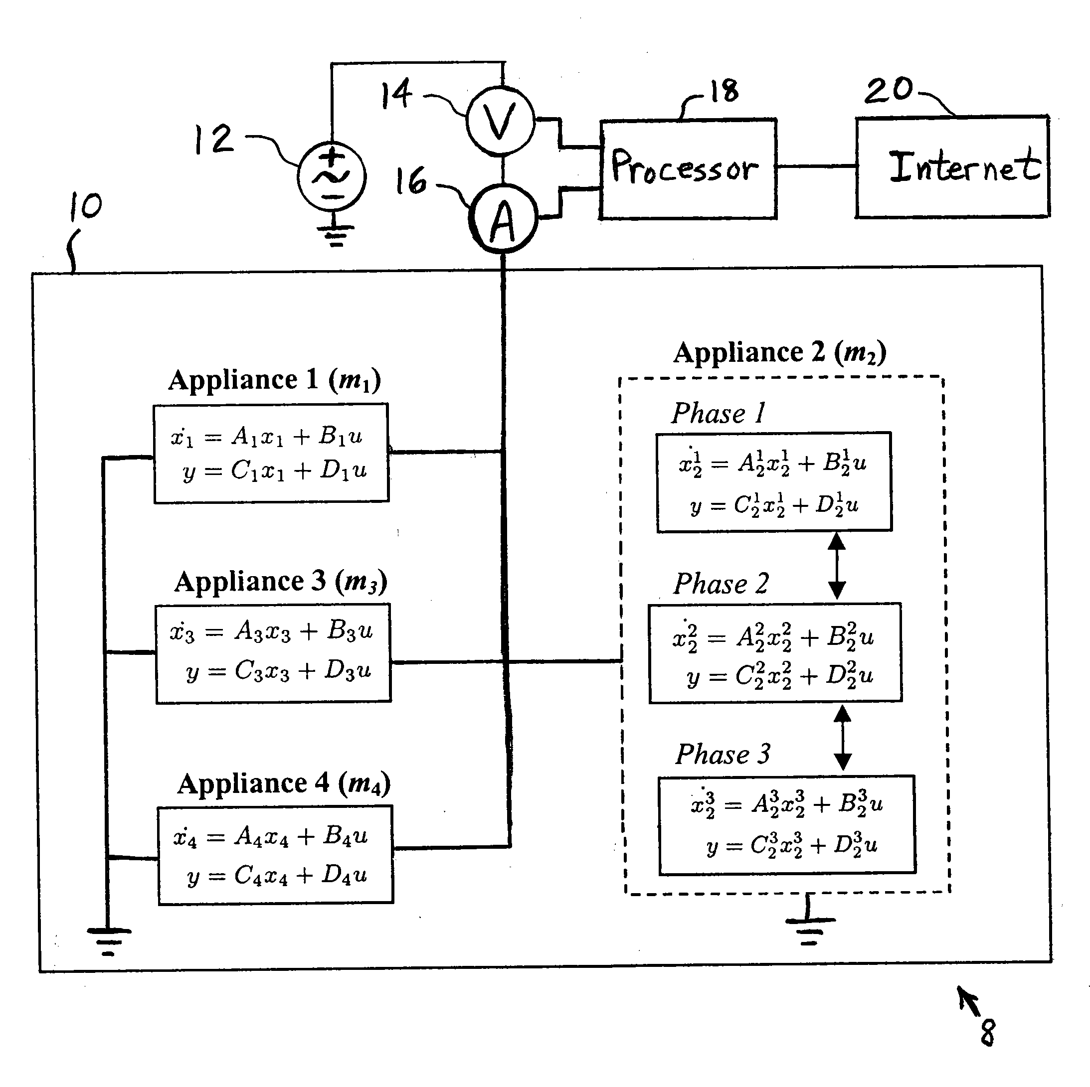
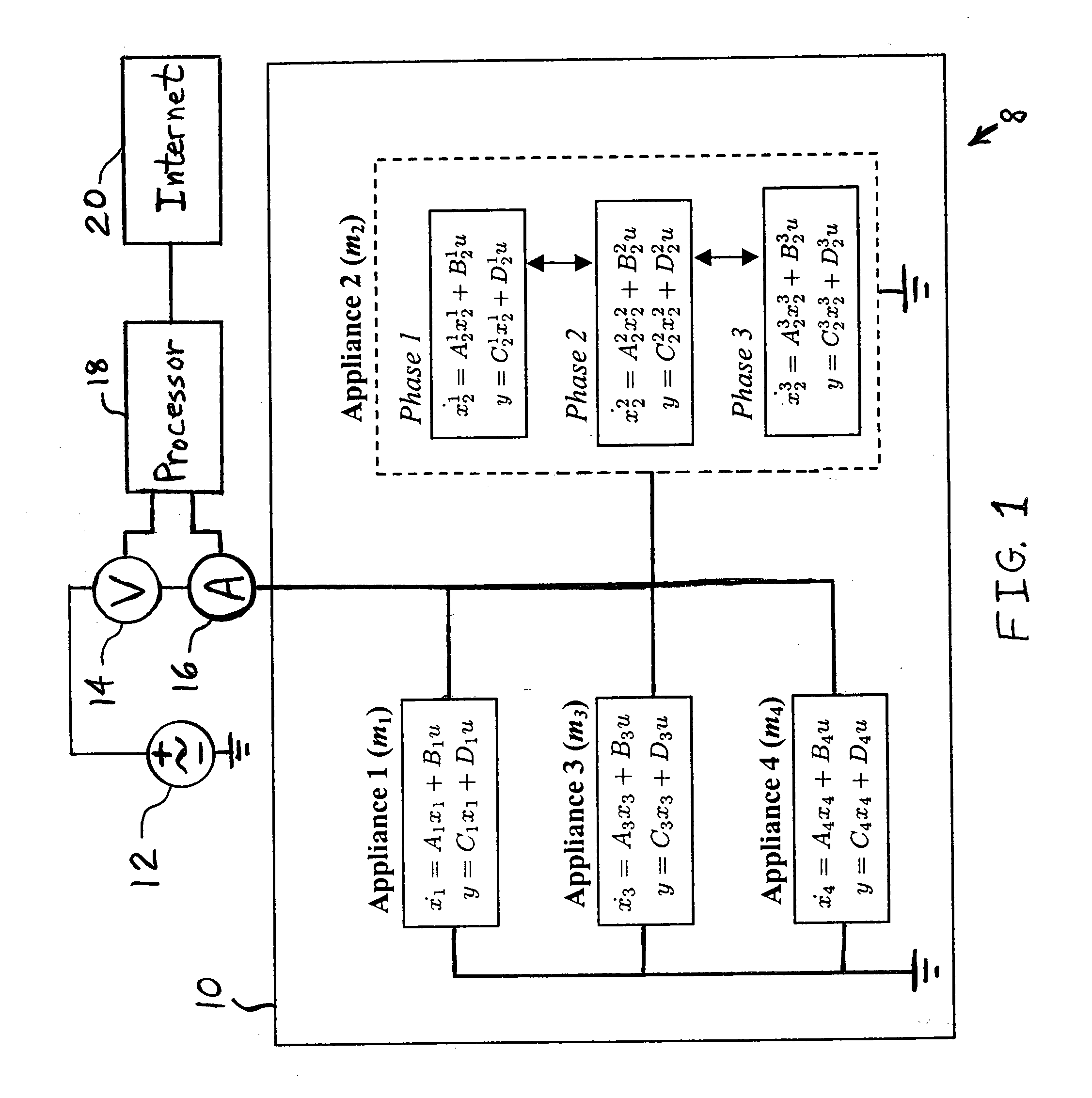
[0046]Shown in FIG. 1 is one embodiment of a non-intrusive load monitoring arrangement 8 of the present invention including appliances 1-4 disposed within a building 10. Appliances 1-4 are power...


PUM


Abstract

A method for non-intrusively monitoring a load including a plurality of appliances includes retrieving a plurality of mathematical models for modeling operation of a respective subset of the appliances. A value of a respective operational parameter is predicted for each of the subsets of appliances. An output of the load is measured. A respective value of each of the operational parameters is calculated based on the mathematical models and the outputs of the load. The predicting, measuring and calculating steps are repeated until a metric pertaining to a difference error between the measured output and the predicted output calculated from the operational parameter and the mathematical models is equal to or below a threshold for one of the subsets of appliances. It is decided that the one subset of appliances is currently operating whose metric pertaining to a difference error is equal to or below the threshold.

Description

BACKGROUND OF THE INVENTION[0001]1. Field of the Invention[0002]The present invention relates to methods for monitoring the electrical load within a building, and, more particularly, to methods for monitoring the electrical load status within a building in a non-intrusive way.[0003]2. Description of the Related Art[0004]The price and consumption of energy throughout the world has been increasing dramatically over recent years and is expected to continue along this trend in the years to come. For example, according to the U.S. Department of Energy Annual Energy Outlook, total residential energy consumption is expected to increase by approximately twenty percent from 2007 to 2030 despite efficiency improvements. This is attributed to a number of factors including a projected twenty-four percent increase in the number of households and an approximately seven percent increase in the share of electricity attributed to “other” appliances such as home electronics. Increases in residential ...

Claims


Application Information

Patent Timeline
Patent Type & Authority Applications(United States)
IPC IPC(8): G06F1/28G06F17/10G06G7/62
CPCG01D4/004G06Q10/04G06Q50/06H02J13/0006H02J2003/007Y02B90/242Y04S10/54Y04S20/322Y04S20/40Y04S10/30Y04S40/22Y02E60/74Y02E60/76Y02B90/245H02J2203/20H02J13/00002H02J2310/70Y02E60/00Y04S40/20Y04S10/50G01D2204/24G01D2204/14Y02B90/20Y04S20/30
Inventor ANDREWS, BURTONBENITEZ, DIEGORAGHUNATHAN, BADRIRAJHANS, AKSHAY
Owner ROBERT BOSCH GMBH
Why Eureka
Try Eureka