PET - MRI hybrid apparatus and method of implementing the same

a hybrid apparatus and image technology, applied in the field of apparatus and methods for noninvasively obtaining images, can solve the problems of general lack of molecular specificity, limited accuracy of anatomical information of pet, and inability to achieve fmri or mri

Inactive Publication Date: 2006-03-09
GACHON UNIV OF IND ACADEMIC COOPERATION FOUND
View PDF18 Cites 92 Cited by
  • Summary
  • Abstract
  • Description
  • Claims
  • Application Information

AI Technical Summary

Benefits of technology

[0014] In accordance with another embodiment of the present invention, there is provided an imaging apparatus for providing anatomical information, as well as molecular and functional information, of a subject. The apparatus comprises: a first scanner for obtaining said anatomical information, as well as functional information on said subject; a second scanner for obtaining said molecular and functional information; a RF+ magnetic shield for sheltering a space including said first scanner from external RF fields, and for further preventing magnetic fields of said first scanner from leaking outside; a magnetic shield for sheltering a space including said second scanner from said magnetic fields out of said first scanner; a transferring railway running along a line from said first scanner via said RF+ magnetic shield and said magnetic shield to said second scanner; and a bed movable along said transferring railway and for supporting said subject.

Problems solved by technology

MRI is essentially a morphological or anatomical imaging tool rather than functional, and thus lacks molecular specificity.
Theses capabilities are generally lacking in fMRI or MRI.
However, PET is limited in providing accurate anatomical information since it has inherently lower spatial resolution.
Contrary to PET, however, MRI is capable of providing detailed anatomical information on human tissues, but cannot provide molecular and functional information.
However, none of the prior attempts achieved any practical success.
Therefore, even if the MRI and PET images are obtained, it is very difficult to combine them with a precision that is needed in image fusion.
In addition, because the two images (i.e., one from MRI and the other from PET) are taken at different places (different environments or conditions) and times (metabolic changes will occur between them), it is highly possible that the conditions between such times and places may change and thus inconsistency is likely to be introduced.
In other words, it is generally not suitable to combine an anatomical image from the MRI device 120 (or an oxygen consumption or hemodynamic image from fMRI) with a molecular image from the PET / CT device 130 in a conventional setting, especially in brain imaging due to the fine details of the brain structures.

Method used


Image

  • PET - MRI hybrid apparatus and method of implementing the same
  • PET - MRI hybrid apparatus and method of implementing the same
  • PET - MRI hybrid apparatus and method of implementing the same

Examples


first embodiment

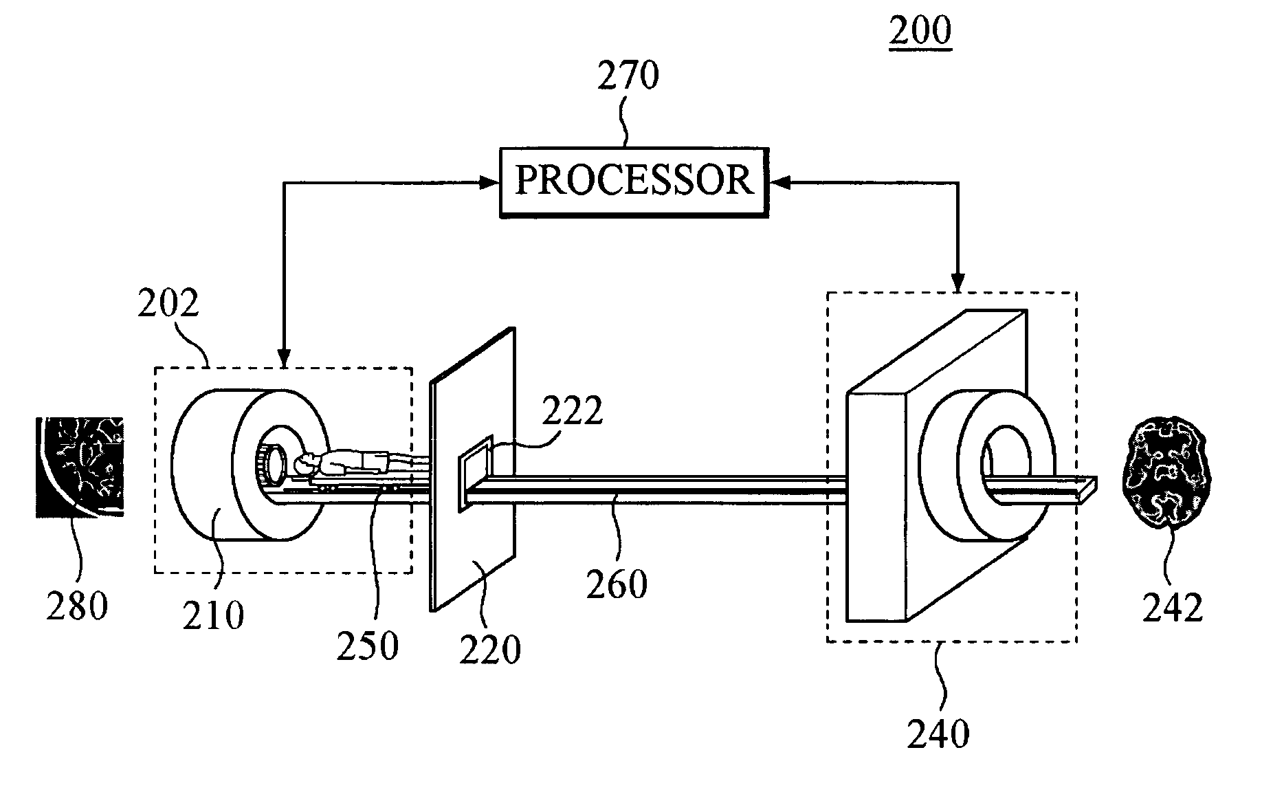
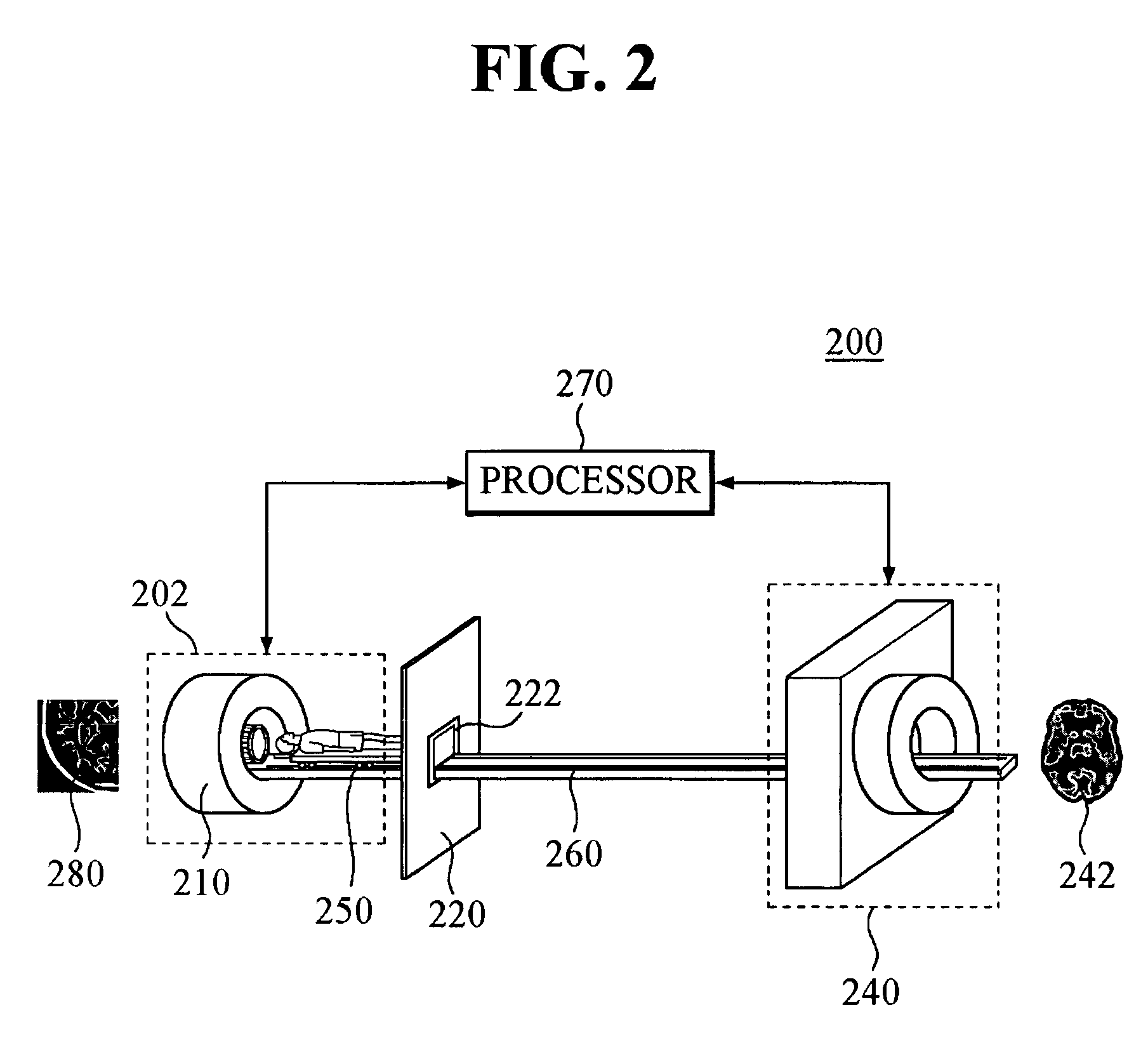
[0050] The patient bed 460 supports and moves a patient back and forth between the UHF-MRI scanner 410 and the HRRT-PET scanner 440. It can locate a patient to a RF coil of the UHF-MRI scanner 410, like the bed 250 of the

[0051] The transferring railway 460 runs between the UHF-MRI scanner 410 and the HRRT-PET scanner 440. The railway 460 is desirably required to maintain a prescribed relationship between image-taking origins for the UHF-MRI scanner 410 and the HRRT-PET scanner 440 when the patient is transferred along the railway between the scanners.

[0052] The transferring railway 460 further comprises a rotary table 462 to rotate a patient by 180 degrees, which is installed between the RF+ magnetic shield 420 and the magnetic shield 430. After being out of the UHF-MRI scanner 410, the rotary table 462 makes it easy for a patient's head to enter the HRRT-PET scanner 440, whose bore is too small to pass a patient's trunk.

[0053] The imaging processor 470 performs the necessary algo...

second embodiment

[0055]FIG. 6 illustrates a method performed in the second embodiment in accordance with the present invention.

[0056] In step 620, a patient is fixed on the patient bed 450. The patient bed 450 moves in a manner as to direct the head first along the railway 460 to transfer toward the UHF-MRI scanner 410. When the patient is moving, the RF+ magnetic shield 420 should be opened and the magnetic shield 430 should be closed. After the patient's feet pass through the shutter, the shutter then closes. The patient bed 450 continues to move toward the UHF-MRI scanner 410 until the patient's head is located inside an RF coil 414 of the UHF-MRI scanner 410.

[0057] In step 630, the UHF-MRI scanner 410 applies RF fields and gradients. The patient emits RF signals, which belong to the patient's head inserted within the RF coil 414. In general, the higher the magnetic fields are, the more larger and reliable and accurate information can be obtained. Thus, compared with the conventional MRI scanner...


PUM


Abstract

There is provided a PET-MRI hybrid apparatus and method for integrating a PET image and an MRI image so that anatomical, hemodynamical and molecular information on human tissues are simultaneously presented in a single image. The PET-MRI hybrid system comprises a first scanner for obtaining anatomical and hemodynamical information, and a second scanner for obtaining molecular and functional information on the human tissues. Along a path between the first scanner and the second scanner, a transferring railway system which includes runs, and a movable bed for supporting a subject installed on the railway. The PET-MRI hybrid system also comprises a “RF+ magnetic” shield and a “magnetic” shield between path between the first scanner and the second scanner, which switch between an open status and a close status in a completely synchronized manner to assure a complete magnetic shield for the PET system at any given time. The subject is fastened on the bed and transferred along the railway between the first and second scanner to provide accurately fused MRI and PET images.

Description

FIELD OF THE INVENTION [0001] The present invention generally relates to an apparatus and method for non-invasively obtaining an image featuring information on internal human tissues, and more particularly to an apparatus and method for integrating positron emission tomography (PET) and magnetic resonance imaging (MRI) to provide a single high spatial resolution image which features anatomical information, as well as molecular and functional information on the internal human tissues. BACKGROUND OF THE INVENTION [0002] PET was first developed in 1975 by two different groups of scientists. The first group is comprised of Dr. Zang-Hee Cho, et al. at University of California at Los Angeles (UCLA), while the second group is composed of Dr. M. Ter-Pogossian and Dr. M. Phelps, et al. at Washington University, St. Louis, Mo. Since then, PET has been further developed and innovated by several different commercial companies, including CPS-CTI. PET has been the only machine capable of performi...

Claims


Application Information

Patent Timeline
Patent Type & Authority Applications(United States)
IPC IPC(8): A61B5/05
CPCG01R33/20G01R33/422A61B6/037G01T1/1603G01T1/2985G01R33/481A61B5/055
Inventor CHO, ZANG HEEKIM, YOUNG BOLEE, CHEOL OK
Owner GACHON UNIV OF IND ACADEMIC COOPERATION FOUND
Why Eureka
Try Eureka