
Stand of a display device

a display device and stand technology, applied in the field of stands, can solve the problems of limited height adjustable range, difficult height adjustment, complicated structure of the stand, etc., and achieve the effect of convenient adjustment of the height/tilt of the display device, simple structure and less number of parts

Inactive Publication Date: 2009-03-03
LG ELECTRONICS INC
View PDF22 Cites 31 Cited by
  • Summary
  • Abstract
  • Description
  • Claims
  • Application Information

AI Technical Summary

Benefits of technology

The present invention is a stand of a display device that solves problems of existing stands by providing a sliding unit for adjusting the height and a hinge connection unit for adjusting the tilt. The stand has a simple structure with fewer parts, prevents deterioration of the spring tension in an auxiliary link when kept in a folding state for a long time, automatically fixes the main link when folded without a separate fixing unit, and reduces the volume in the folding state to reduce distribution costs. The stand allows for convenient adjustment of the display device's height and angle, simplifies the stand's structure, and reduces the stand's folded volume.

Problems solved by technology

In the related art stand of a display device having such a dual hinge structure, the tilt of the display device can be adjusted but it is difficult to adjust the height.
Even when the height is adjustable, the height adjustable range is limited by the length of the hinge connection unit.
When a separate height adjustable unit is used, the structure of the stand is complicated.
Furthermore, since the separate unit is formed of metal and coupled to the stand, it is vulnerable to an external impact.
Furthermore, the number of parts increases, thereby increasing the overall volume.
Therefore, the number of parts increases, thereby increasing the manufacturing cost.
However, when the stand keeps its folding state for a longtime, the spring also keeps it tensioned state for a long time, thereby deteriorating the elastic property of the spring.
This increases the manufacturing cost.
This is troublesome for the user.

Method used


Image

  • Stand of a display device
  • Stand of a display device
  • Stand of a display device

Examples


Embodiment Construction

[0040]Reference will now be made in detail to the preferred embodiments of the present invention, examples of which are illustrated in the accompanying drawings. Wherever possible, the same reference numbers will be used throughout the drawings to refer to the same or like parts.

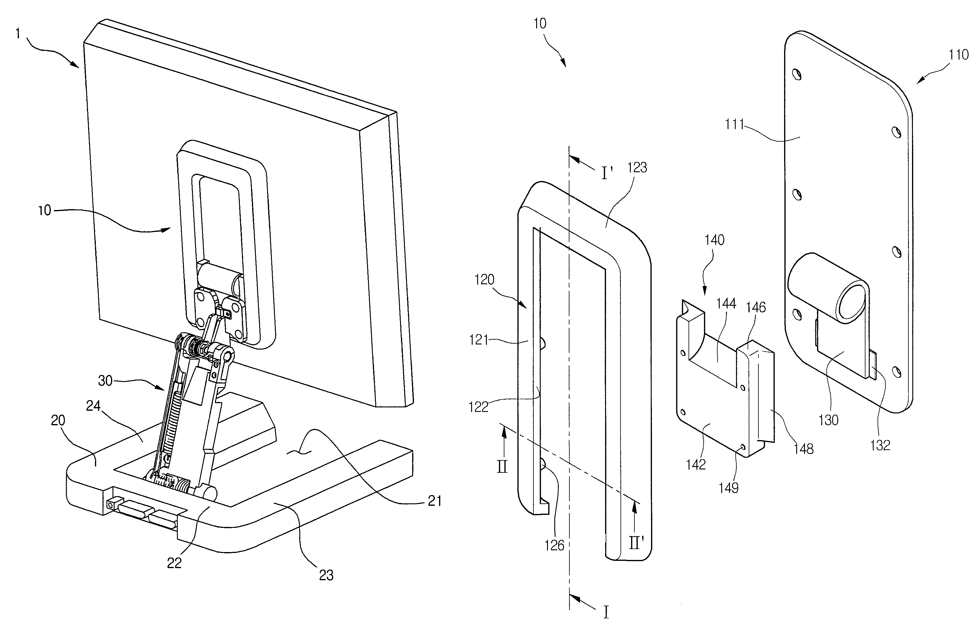
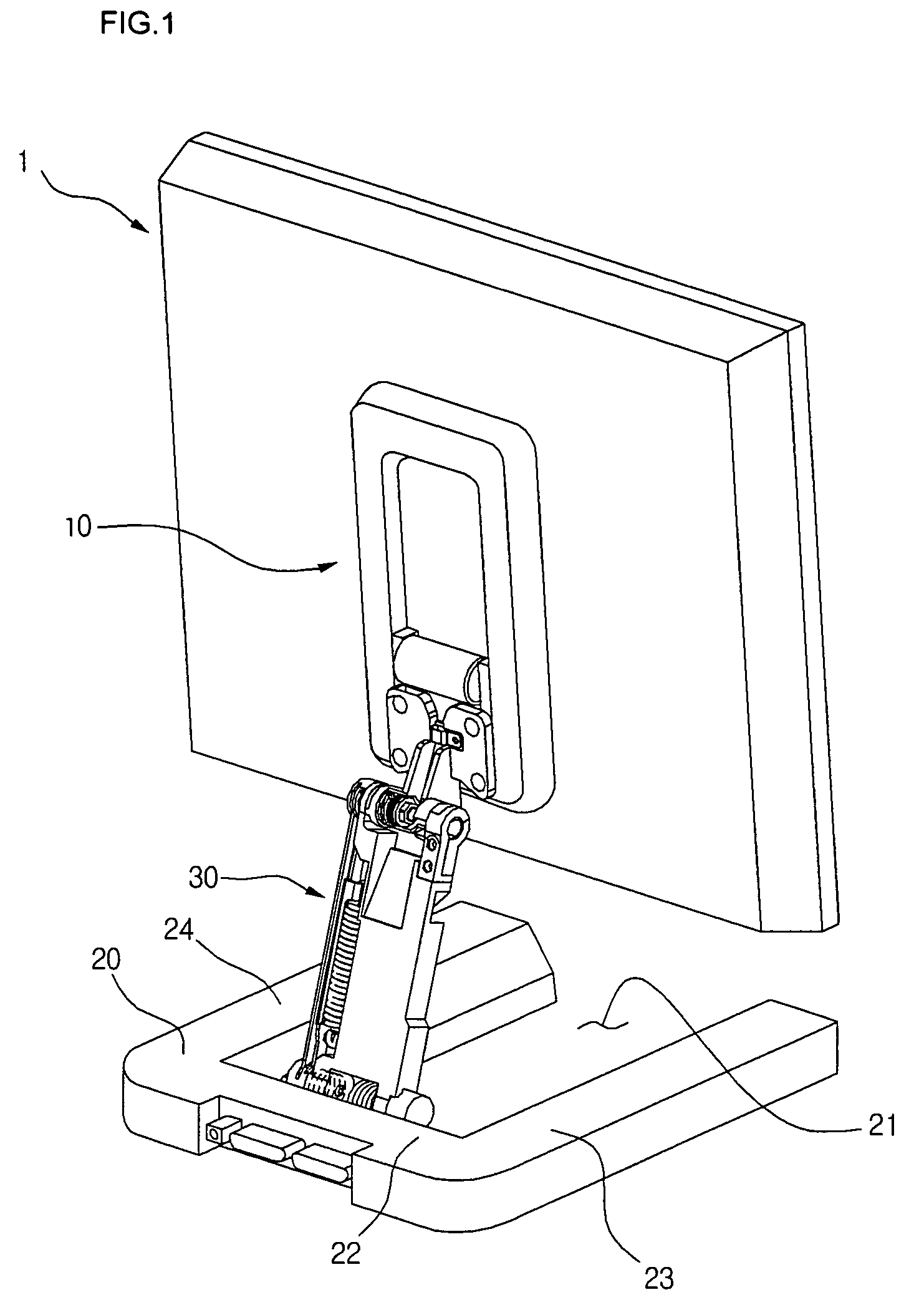
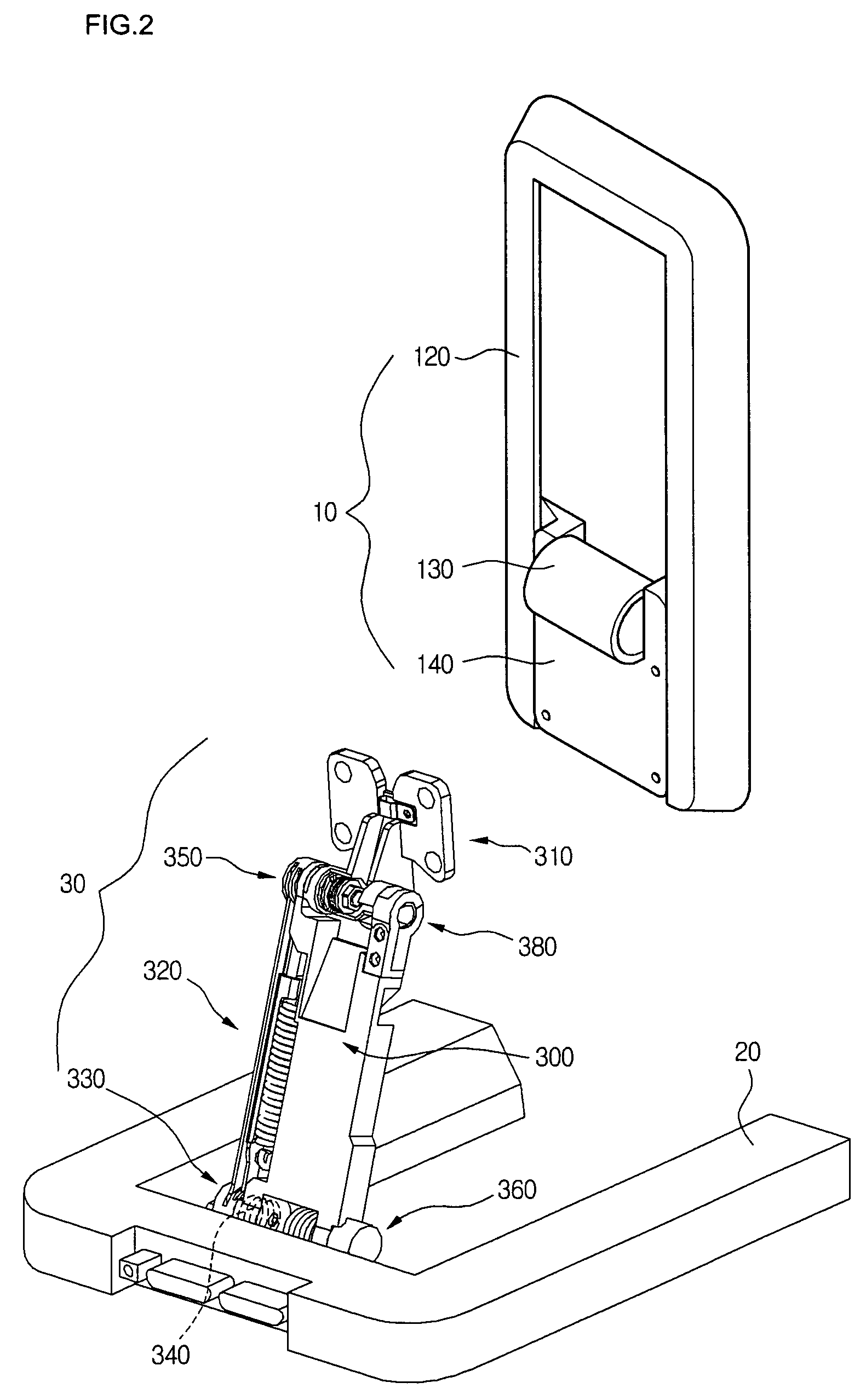
[0041]FIG. 1 is a rear perspective view of a display device to which a stand of a display device according to an embodiment of the present invention is applied and FIG. 2 is a rear perspective view of the stand of a display device of FIG. 1 when a sliding unit is separated.

[0042]Referring to FIG. 1, a stand of a display device according to an embodiment of the present invention includes a sliding unit 10 for adjusting a height of a display device 1, a base unit 20 placed on a horizontal surface to support the display device, and a hinge connection unit 30 having a first end pivotally coupled to the sliding unit 10 and a second end pivotally coupled to the base unit.

[0043]Referring to FIG. 2, the sliding unit...


PUM


Abstract

Provided is a stand of a display device that can be reduced in its volume and allows a user to adjust a position of a display device more conveniently. The stand of a display device includes: a sliding unit for vertically moving a display device, the sliding unit mounted on the display device; a base unit for supporting the display device; and a hinge connection unit having a first end pivotally coupled to the sliding unit and a second end pivotally coupled to the base unit.

Description

BACKGROUND OF THE INVENTION[0001]1. Field of the Invention[0002]The present invention relates to a stand, particularly height / tilt adjustable stand of a display device, and more particularly, to a height / tilt adjustable stand of a display device that can prevent the property of a spring tensioned in an auxiliary link from being deteriorated when the stand keeps its folding state for a long time, allow a main link to be automatically fixed when the stand folds; stably maintain the folding state of the stand, and be reduced in its volume in the folding state to reduce the package volume.[0003]2. Description of the Related Art[0004]Generally, a stand for a display device has a variety of adjusting units for rotating, tilting, swiveling, raising, and lowering the display device.[0005]A related art stand having two hinges for adjusting its height / tilt includes a base unit placed on a horizontal surface and a hinge connection unit for connecting the base unit to a display device body to a...

Claims


Application Information

Patent Timeline
Patent Type & Authority Patents(United States)
IPC IPC(8): F16M13/00H05K7/14
CPCF16M11/04F16M11/046F16M11/10F16M11/2014F16M11/24F16M11/38F16M2200/024F16M2200/044H04N5/655
Inventor LEE, JIN BUM
Owner LG ELECTRONICS INC
Learn More