Reagent tube for top loading analyzer

a top loading analyzer and reagent tube technology, applied in chemical analysis using combustion, instruments, measurement devices, etc., can solve the problems of significant amount of combustion oxygen used in the filling of the fixed ballast chamber, significant amount of time for analysis, and considerable time, expense, and manpower. achieve the effect of easy removal

Active Publication Date: 2009-03-03
LECO CORPORATION
View PDF3 Cites 8 Cited by
  • Summary
  • Abstract
  • Description
  • Claims
  • Application Information

AI Technical Summary

Benefits of technology

[0008]The system of the present invention satisfies this need by providing a reagent assembly for a combustion furnace having a combustion tube. The reagent assembly employs a reagent tube which is packed with a reagent and is concentrically positioned in the combustion tube. The reagent tube is sealably and removably coupled to an open end of the combustion tube such that, when the reagent is depleted, the reagent tube can be easily removed without disassembly of the furnace or changing the combustion tube.
[0010]In all embodiments, the reagent tube is packed with reagents and is coupled to a fitting which is easily removed from the combustion furnace and combustion tube and which allows the reagent tube containing an exhausted reagent to be removed from the top of the combustion tube, thereby eliminating the need to remove and / or replace the entire combustion tube from the furnace once the reagent has been expended. In a preferred embodiment of the invention, the fitting includes a twist-lock cap associated with the reagent tube to facilitate its removal. Such a system thereby allows for on-the-fly micro analysis of a sample which utilizes a reagent to remove the excess oxygen and allows the reagent to be replenished as necessary without the time and effort required by existing systems.

Problems solved by technology

The amount of combustion oxygen used in filling the fixed ballast chamber is significant, and an analysis takes a significant amount of time for the combustion and ballast chamber filling.
One difficulty with an on-the-fly analysis system is that, for such micro analysis utilizing a helium carrier gas, an influx plug of excess oxygen is employed to fully combust the sample, and the remaining oxygen must be eliminated prior to detection by flowing the gaseous byproducts of combustion through a reduction reagent, such as copper wire strips.
Since combustion takes place at a temperature of nearly 1000° C., this requires considerable time, expense, and manpower, since the furnace must first be cooled, opened, the combustion tube disassembled, and frequently a new combustion tube with a new reagent installed.

Method used


Image

  • Reagent tube for top loading analyzer
  • Reagent tube for top loading analyzer
  • Reagent tube for top loading analyzer

Examples


Embodiment Construction

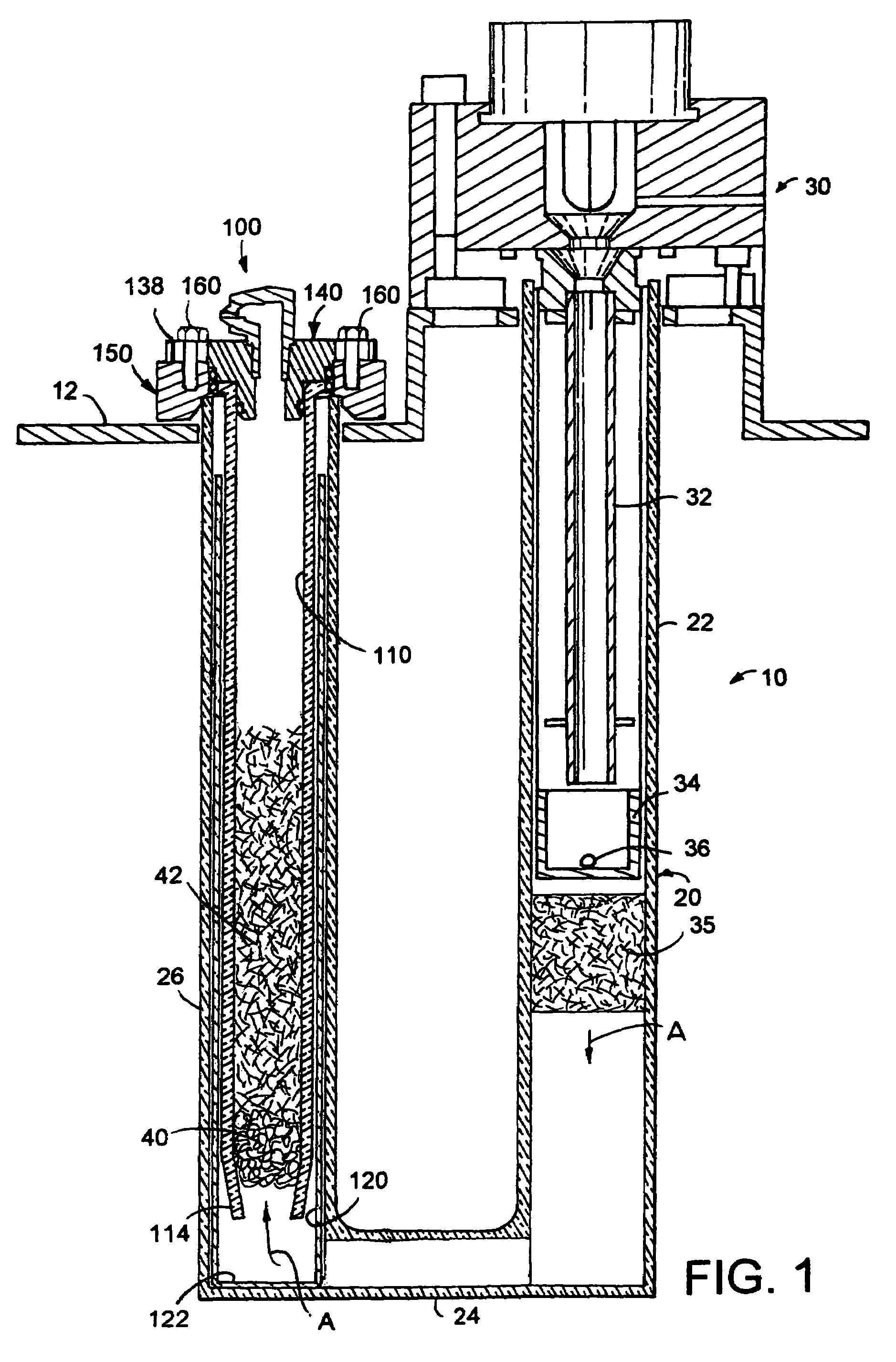
[0018]Referring initially to FIG. 1, there is shown an analytical furnace 10 embodying a reagent assembly 100 of the present invention. Furnace 10 is a resistance heating furnace including a generally U-shaped quartz combustion tube 20 having a generally cylindrical vertically extending first or combustion leg 22, a transverse coupling conduit 24, and a vertically upwardly extending second or reagent leg 26. The combustion tube, thus, generally has cylindrical sections 22 and 26 which are joined by the transverse conduit 24. The furnace 10 can generally be of the type disclosed in U.S. Pat. No. 4,622,009, the disclosure of which is incorporated herein by reference, which heats a sample 36 dropped by a sample load assembly 30 of the type disclosed in U.S. Pat. No. 6,291,802, the disclosure of which is incorporated herein by reference, through an oxygen lance and sample introduction tube 32 into a crucible 34. Crucible 34 can be of the type disclosed in U.S. Pat. No. 6,270,727, the di...


PUM

PropertyMeasurementUnit
temperatureaaaaaaaaaa
thicknessaaaaaaaaaa
thicknessaaaaaaaaaa

Abstract

A reagent assembly for a combustion tube includes a reagent tube which is sealably and removably coupled to the open end of the combustion tube such that, when the reagent in the reagent tube is depleted, it can be easily removed without disassembly of the furnace or changing the combustion tube. The reagent tube includes a twist-lock cap to facilitate removal of the reagent tube.

Description

BACKGROUND OF THE INVENTION[0001]The present invention relates to elemental analyzers and particularly an analyzer which employs a reagent assembly which is easily removable from the combustion chamber.[0002]A determination of concentration of elements, such as carbon, hydrogen, sulfur, and nitrogen, in an organic sample is desirable for a variety of reasons. In recent years, the food market in particular has become interested in determining the amount of protein in an organic sample, which can be determined by the nitrogen content. Further, the sulfur content, as well as the carbon-to-hydrogen ratio, is desirable in the characterization of coal and coke samples, as are the carbon, hydrogen, and nitrogen ratios in a variety of other organic materials.[0003]Elemental analyzers are commercially available from the Assignee of the present application, Leco Corporation of St. Joseph, Mich., which manufactures CHN analyzers, which are sold under the trademark TRUSPEC®. The analyzer may em...

Claims


Application Information

Patent Timeline
Patent Type & Authority Patents(United States)
IPC IPC(8): G01N31/12
CPCG01N31/005G01N31/12
Inventor ROHALY, STEVEN J.MITCHELL, JOEL C.
Owner LECO CORPORATION
Why Eureka
Try Eureka