
Illumination apparatus and image-taking apparatus

a technology of image-taking apparatus and illumination apparatus, which is applied in the field of illumination apparatus, can solve the problems of poor inability to increase the design freedom of the camera body, and the optical system of illumination, and achieve the effect of wide design freedom of the exit surface shap

Inactive Publication Date: 2009-03-03
CANON KK
View PDF3 Cites 3 Cited by
  • Summary
  • Abstract
  • Description
  • Claims
  • Application Information

AI Technical Summary

Benefits of technology

[0012]It is one exemplary object of the present invention is to provide an illumination apparatus and an image-taking apparatus having the same, which have a wide design freedom of the exit surface shape, and provide an approximately uniform light distribution characteristic to a necessary irradiation range.

Problems solved by technology

However, the conventional camera having the illumination optical system is problematic in poor design freedom of the camera body.
However, as the rotationally central axis of the Fresnel lens is perpendicular to the Fresnel surface similar to prior art, the illumination optical system disclosed in this reference has a limit to correct a parallax with an optical axis of the image-taking lens and cannot increase the design freedom of the camera body.
The exited light spreads little, converges in a certain direction, and also causes the non-uniform light distribution.

Method used


Image

  • Illumination apparatus and image-taking apparatus
  • Illumination apparatus and image-taking apparatus
  • Illumination apparatus and image-taking apparatus

Examples


Embodiment Construction

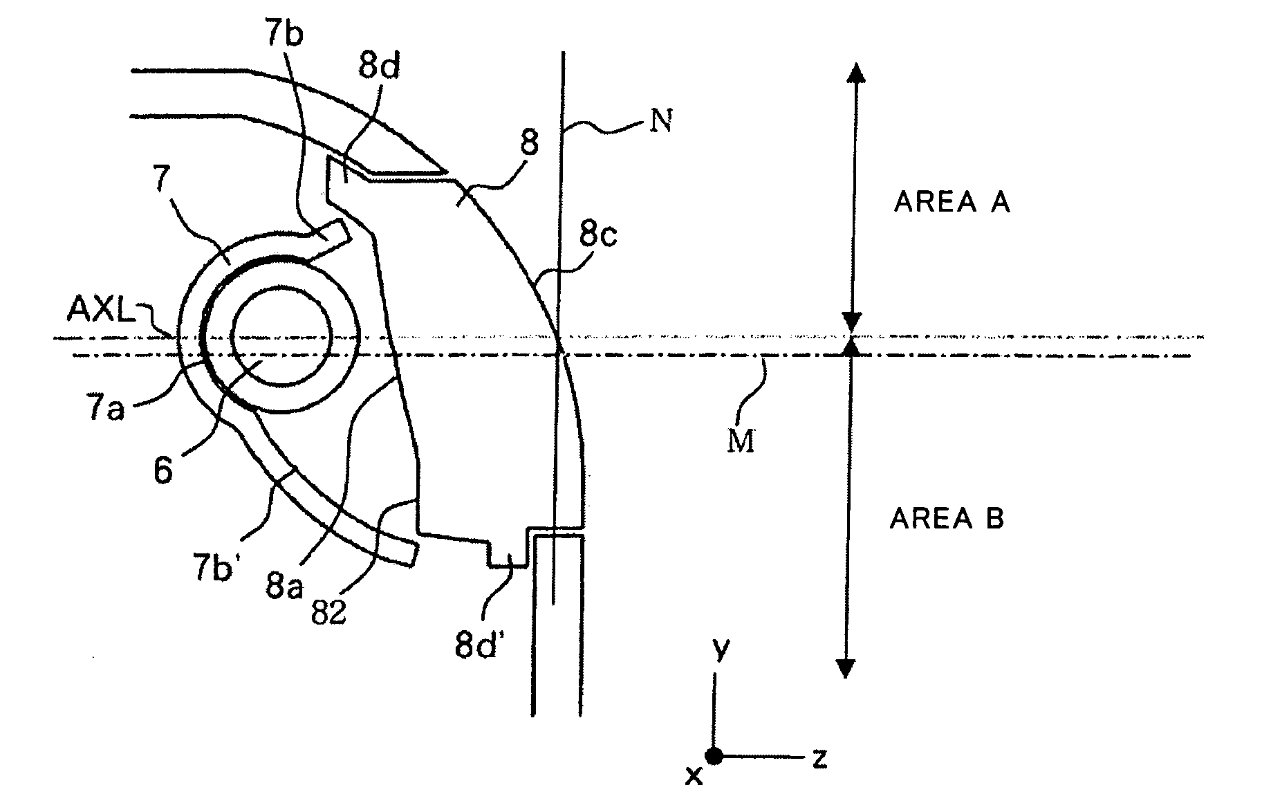
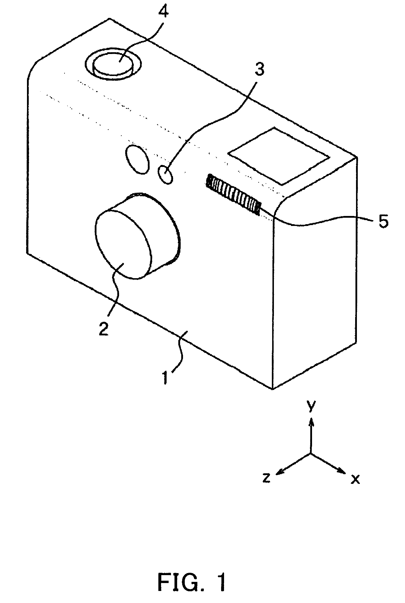
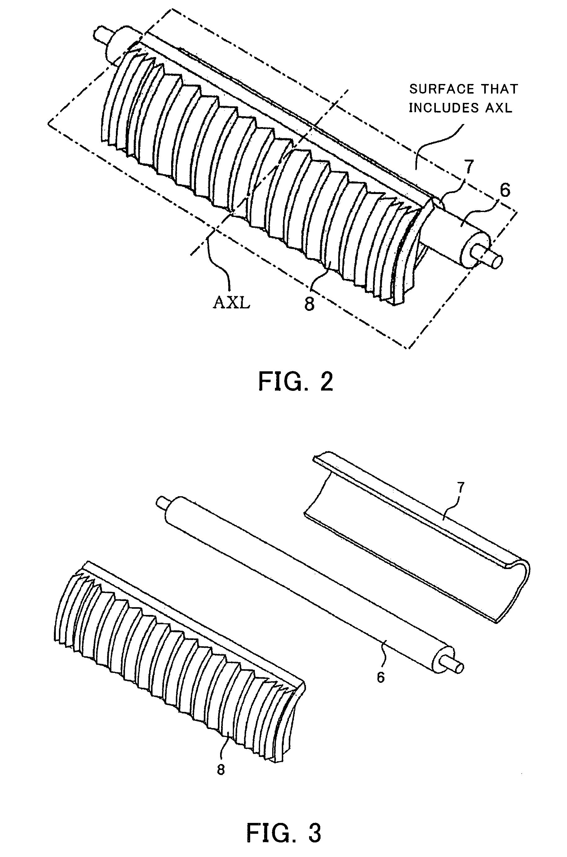
[0024]Referring now to FIGS. 1 to 5, a description will be given of one embodiment of the present invention. FIG. 1 is a front perspective view of a camera as an image-taking apparatus. FIG. 2 is a perspective view of an illumination apparatus assembled in the camera. FIG. 3 is an exploded perspective view of FIG. 2. FIGS. 4A, 4B, 5A and 5B show an optical arrangement of optical components in the illumination apparatus.

[0025]In these figures, 1 denotes a camera body, and has a zooming lens barrel 2 at its front center. The lens barrel 2 holds an image-taking lens, such as a zooming lens (not shown) and a focusing lens, and provides zooming and focusing as it moves back and forth in the optical axis direction.

[0026]3 denotes a finder provided above the lens barrel 2. 4 denotes a release button provided on a top surface of the camera body 1. A first stroke operation of the release button 4 starts an image-taking preparatory action, such as a focus detection and a photometric action, a...


PUM


Abstract

In an illumination apparatus, an optical element has an exit surface in which an inclination to a perpendicular to an irradiation optical axis in a first area is greater than that of a second area, and the inclination of the first area gradually increases in order from the irradiation optical axis, an intermediate part and a periphery of the exit surface. The first and second areas are defined as those divided by an interface surface that includes an irradiation optical axis and is orthogonal to a plane that is orthogonal to a longitudinal direction of the light source. A first reflective surface reflects first light to the intermediate part in the first area. A second reflective surface reflects second light to the periphery in the second area.

Description

BACKGROUND OF THE INVENTION[0001]The present invention relates to an illumination apparatus that irradiates light from a light source, and an image-taking apparatus having the illumination apparatus.[0002]An illumination apparatus for use with a conventional image-taking apparatus, such as a camera, includes a light source, a reflector and an optical element, such as a Fresnel lens, that are used to introduce the light from the light source to a front or subject side.[0003]A variety of proposals have been made to such an illumination apparatus so as to reduce its size and efficiently condense the light that is emitted from the light source in various directions, into a necessary irradiation angle of view. See Japanese Utility-Model Application, Publication No. 2-138733 and Japanese Patent Application, Publication No. 7-270867.[0004]For example, the illumination apparatus shown in FIG. 6 includes a 10 having a reflective surface, and an optical element 11 that has an incident surface...

Claims


Application Information

Patent Timeline
Patent Type & Authority Patents(United States)
IPC IPC(8): G03B15/02F21V5/04F21V7/00F21V13/04F21Y103/00G03B15/03G03B15/05H04N5/222
CPCG03B15/05G03B2215/0503G03B2215/0578G03B2215/0582G03B2215/0592
Inventor KOJIMA, NOBUHISA
Owner CANON KK
Learn More